Kia Rio: Air Conditioning System / Photo Sensor (FATC only)
Description and operation
| Description |
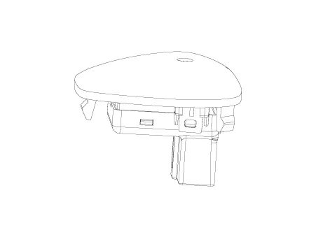
The photo sensor is located at the center of defrost nozzles.
The photo sensor contains a photovoltaic (sensitive to sunlight) diode. The solar radiation received by its light receiving portion, generates an electromotive force in proportion to the amount of radiation received which is transferred to the automatic temperature control module so that the solar radiation compensation will be performed.
Repair procedures
| Inspection |
| 1. |
Turn the ignition switch ON. |
| 2. |
Connect the GDS. |
| 3. |
Emit intensive light toward photo sensor using a lamp, and check the output voltage change. |
| 4. |
The voltage will rise with higher intensive light and reduce with lower intensive light.
|
| Replacement |
| 1. |
Disconnect the negative (-) battery terminal. |
| 2. |
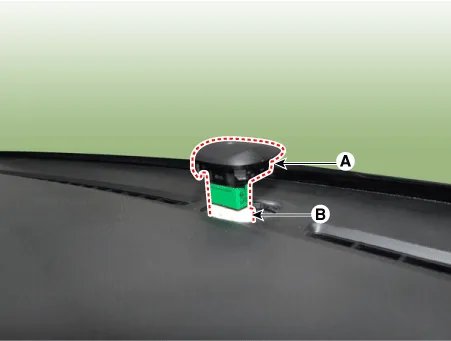
With a flat-head screwdriver, remove the photo sensor (A) from the center of defrost nozzle after disconnecting the connector (B).
|
| 3. |
Install in the reverse order of removal. |
Description and operation Description The evaporator temperature sensor will detect the evaporator core temperature and interrupt compressor relay power in order to prevent evaporator freezing by excessive cooling.
Description and operation Description The ambient temperature sensor is located at the front of the condenser and detects ambient air temperature.
Other information:
Kia Rio 2017-2023 YB Service Manual: Power Windows
Components and components location Component Location 1. Driver power window switch 2. Assist power window switch 3. Rear power window switch 4. Front window motor 5. Rear window motor Description and operation Safety Function of Power Window When driver door power win
Kia Rio 2017-2023 YB Service Manual: Heater & A/C Control Unit (MANUAL)
Components and components location Components Connector pin function NO. Connector A Connector B 1 Low Battery 2 Common ISG Battery 3 High Illumination (+)
Categories
- Manuals Home
- Kia Rio Owners Manual
- Kia Rio Service Manual
- Body (Interior and Exterior)
- Timing Chain
- Features of your vehicle
- New on site
- Most important about car
