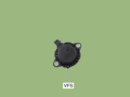
Kia Rio: Engine Control System / Variable Force Solenoid (VFS)
Description and operation
| Description |
Continuous Variable Valve Timing (CVVT) system advances or retards the valve timing of the intake and exhaust valve in accordance with the ECM control signal which is calculated by the engine speed and load.By controlling CVVT, the valve over-lap or under-lap occurs, which makes better fuel economy and reduces exhaust gases (NOx, HC) and improves engine performance through reduction of pumping loss, internal EGR effect, improvement of combustion stability, improvement of volumetric efficiency, and increase of expansion work.This system consist of the Variable Force Solenoid (VFS) which supplies the engine oil to the cam phaser or cuts the engine oil from the cam phaser in accordance with the ECM PWM (Pulse With Modulation) control signal, the Cam Phaser which varies the cam phase by using the hydraulic force of the engine oil.Variable force solenoid (VFS) [intake] changes its force depending on the PWM duty to control the stroke of the CVVT oil control valve (OCV) [intake] bolt. The delivered oil rotates the rotor connected to the camshaft of the cam pager and rotates the camshaft to the engine rotating direction (intake advanced / exhaust retarded) or the opposite direction (intake retarded / exhaust advanced) to change the phase angle of the cam.
Variable Force Solenoid (VFS) [Bank 1 / Intake]
Schematic diagrams
| Circuit Diagram |

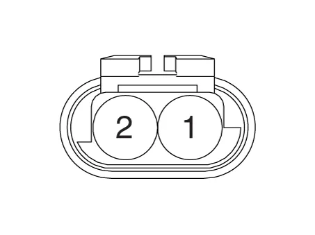
Harness Connector
Repair procedures
| Removal |
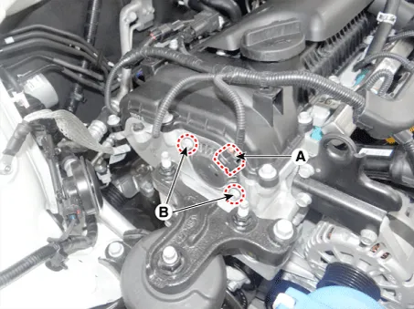
| 1. |
Turn ignition switch OFF and disconnect the battery negative (-) terminal |
| 2. |
Disconnect the VFS connector (A). |
| 3. |
Remove the mounting bolts (B), and then remove the VFS from the engine.
|
| Installation |
|

| 1. |
Install in the reverse order of removal. |
Specifications Specification Item Specification Coil resistance (Ω) 30.0 ~ 35.0 [20°C(68°F)] Description and operation Description Variable Intake manifold Solenoid (VIS) valve is installed on the intake manifold.
Specifications Specification Item Specification Coil resistance (Ω) 30.0 - 35.0 [20°C(68°F)] Pin 2 Description and operation Description Engine coolant stop solenoid valve is installed on the upper side of engine and it is connected to engine coolant stop valve control actuator.
Other information:
Kia Rio 2017-2023 YB Service Manual: Windshield Wiper/Washer
Components and components location Component Location 1. Windshield wiper arm & blade 2. Wiper & washer switch 3. Windshield washer hose & nozzle 4. Wiper motor & linkage assembly 5. Washer motor 6.
Kia Rio 2017-2023 YB Service Manual: Intake Actuator
Description and operation Description The intake actuator is located at the blower unit. It regulates the intake door by signal from control unit. Pressing the intake selection switch will shift between recirculation and fresh air modes.
Categories
- Manuals Home
- Kia Rio Owners Manual
- Kia Rio Service Manual
- Coolant
- Body (Interior and Exterior)
- Maintenance
- New on site
- Most important about car
