Kia Rio: Drive Belt System / Drive Belt Tensioner
Repair procedures
| Removal and Installation |
| 1. |
Remove the engine room under cover. (Refer to Engine and Transaxle Assembly - "Engine Room Under Cover") |
| 2. |
Remove the drive belt. (Refer to Drive Belt System - "Drive Belt") |
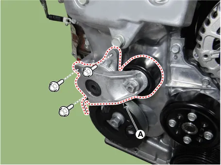
| 3. |
Remove the drive belt tensioner (A).
|
| 4. |
Install in the reverse order of removal. |
| Inspection |
Check the drive belt tensioner for excessive foreign substances, crack, damage or sticking of pivot shaft. Replace if necessary.
Repair procedures Removal and Installation 1. Remove the engine room under cover. (Refer to Engine and Transaxle Assembly - "Engine Room Under Cover") 2.
Repair procedures Removal and Installation 1. Remove the engine room front under cover and RH side cover. (Refer to Engine and Transaxle Assembly - "Engine Room Under Cover") 2.
Other information:
Kia Rio 2017-2023 YB Service Manual: Vanity Lamp
Repair procedures Removal 1. Disconnect the negative (-) battery terminal. 2. Detach the vanity lamp (A) using a flat-tip screwdriver. 3. Disconnect the vanity lamp connector (A).
Kia Rio 2017-2023 YB Service Manual: Sunroof Switch
Components and components location Components Repair procedures Inspection 1. Disconnect the negative (-) battery terminal. 2. Open the sunglass case cover from the overhead console and remove the 2 screws holding the overhead console.
Categories
- Manuals Home
- Kia Rio Owners Manual
- Kia Rio Service Manual
- Maintenance
- Engine Control / Fuel System
- Emission Control System
- New on site
- Most important about car
