
Kia Rio: Drive Belt System / Drive Belt
Repair procedures
| Removal and Installation |
| 1. |
Remove the engine room under cover. (Refer to Engine and Transaxle Assembly - "Engine Room Under Cover") |
| 2. |
Remove the drive belt.
|
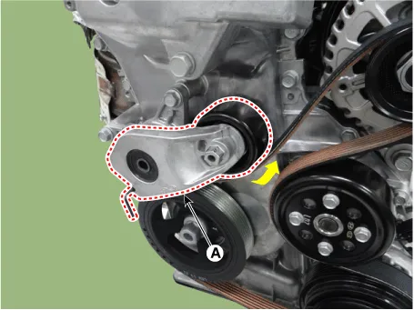
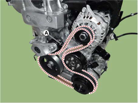
| 3. |
Install in the reverse order of removal. |
| Inspection |
| Drive Belt Inspection |
| 1. |
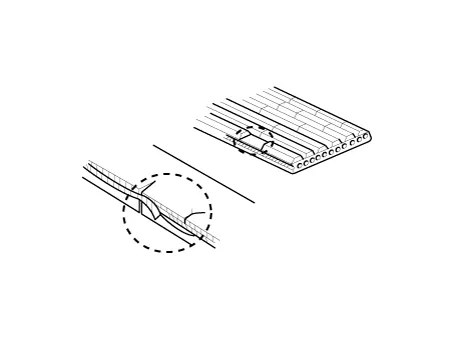
Visually check the belt for excessive wear, frayed cords etc. If any defect has been found, replace the drive belt.
|

| 2. |
Check belt for maintenance and abnormal wear of V-ribbed part. Replace if necessary.
|
Repair procedures Removal and Installation 1. Remove the engine room under cover. (Refer to Engine and Transaxle Assembly - "Engine Room Under Cover") 2.
Other information:
Kia Rio 2017-2023 YB Service Manual: Overhead Console Lamp
Repair procedures Inspection 1. Remove the overhead console lamp assembly then check for continuity between terminals. If the continuity is not as specified, replace the map lamp switch. Removal 1.
Kia Rio 2017-2023 YB Service Manual: A/C Pressure Transducer
Description and operation Description The A/C Pressure Transducer (APT) convert the pressure value of high pressure line into voltage value after measure it. By converted voltage value, engine ECU controls cooling fan by operating it high speed or low speed.
Categories
- Manuals Home
- Kia Rio Owners Manual
- Kia Rio Service Manual
- Heating,Ventilation, Air Conditioning
- Engine Control / Fuel System
- Filler-Neck Assembly
- New on site
- Most important about car
