Kia Rio: Automatic Transaxle System / Automatic Transaxle
Components and components location
| Components |
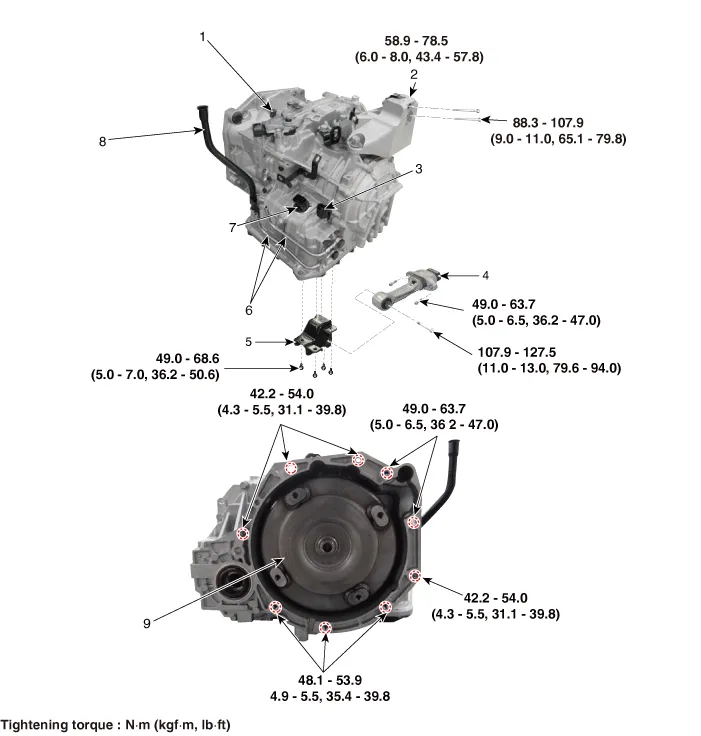
| 1. Inhibitor switch 2. Transaxle support bracket 3. Input speed sensor 4. Roll rod bracket |
5. Roll rod support bracket
6. ATF cooler pipe 7. Main connector 8. ATF filler pipe 9. Torque converter |
Repair procedures
| Removal |
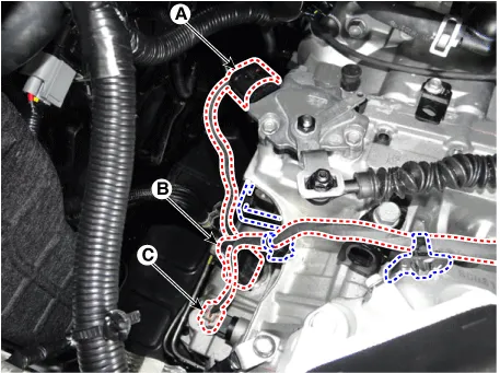
| 1. |
Disconnect the connectors (A, B, C) and then remove the wiring from the brackets.
|
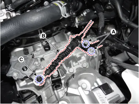
| 2. |
Remove the shift cable (B) after loosening the nut (C) and bolts (A).
|
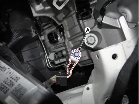
| 3. |
Disconnect the output speed sensor connector (A).
|

| 4. |
Loosen the ground mounting bolt (A).
|
| 5. |
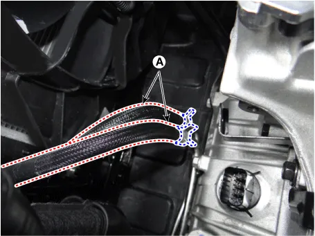
Disconnect the ATF cooler hose (A).
|
| 6. |
Remove the CKP sensor (A) after loosening a bolt.
|
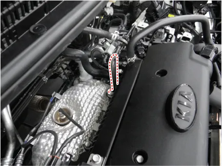
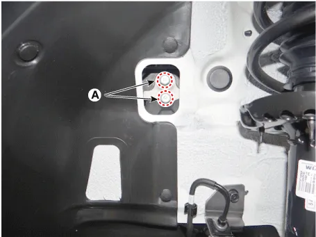
| 7. |
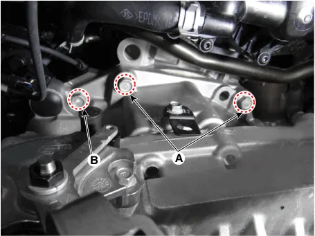
Remove the transaxle upper mounting bolts (A) and the starter mounting bolts (B).
|
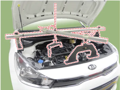
| 8. |
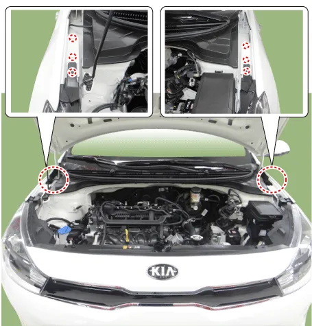
Install the engine support fixture on the engine room.
|
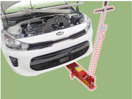
| 9. |
Support the transaxle safely on a jack.
|
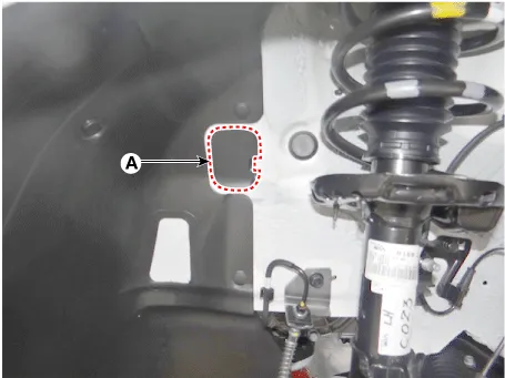
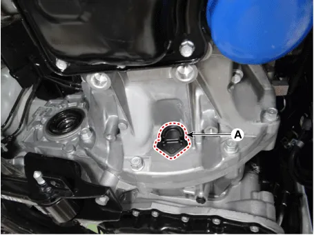
| 10. |
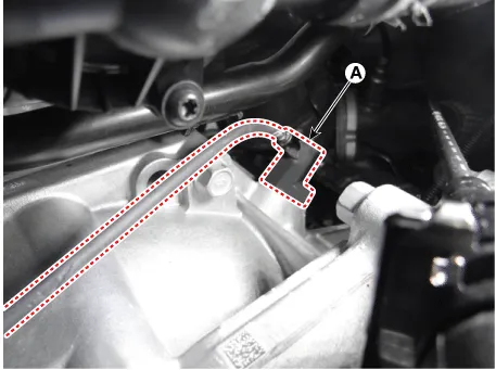
Remove the cover (A).
|
| 11. |
Loosen the transaxle mounting bracket bolts (A).
|
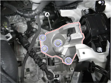
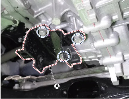
| 12. |
Remove the transaxle support bracket (A).
|
| 13. |
Remove the under cover. (Refer to Engine Mechanical System - "Engine Room Under Cover") |
| 14. |
Remove the drive shaft assembly. (Refer to Driveshaft and Axle - "Front Driveshaft") |
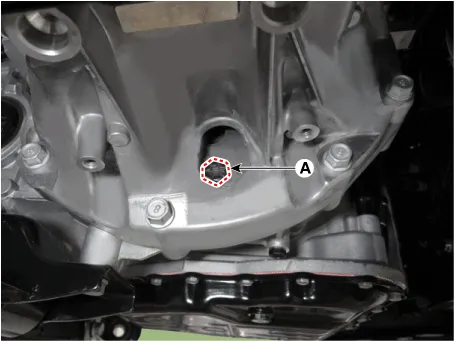
| 15. |
Remove the cover (A).
|
| 16. |
Remove the torque converter mounting bolts (A) by rotating the crankshaft.
|
| 17. |
Support the transaxle safely on a jack. |
| 18. |
Remove the roll rod bracket after removing bolt (A, B).
|

| 19. |
Remove the roll rod support bracket (A).
|
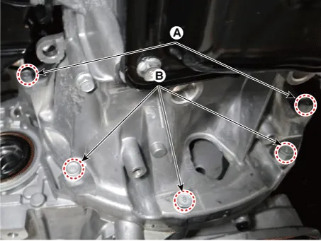
| 20. |
Loosen the transaxle lower mounting bolts (A, B).
|


| 21. |
After separating the transaxle from the engine, remove the transaxle by lowering the jack slowly.
|
| Installation |
| 1. |
Install in the reverse order of removal.
|

Repair procedures Repair procedures Torque Converter Stall Test This test measures the maximum engine speed when the select lever is at the "D" or "R" position and the torque converter stalls to test the operation of the torque converter, starter motor and one-way clutch operation and the holding performance of the clutches and brakes in the transmission.
Description and operation Description Brakes The automatic transaxle (A4CF1) uses the low and reverse brake and the second brake. The low and reverse brake is fixed by the low and reverse annulus gear and overdrive planetary carrier.
Other information:
Kia Rio 2017-2023 YB Service Manual: Power Windows
Components and components location Component Location 1. Driver power window switch 2. Assist power window switch 3. Rear power window switch 4. Front window motor 5. Rear window motor Description and operation Safety Function of Power Window When driver door power win
Kia Rio 2017-2023 YB Service Manual: Power Mosfet (FATC)
Repair procedures Inspection 1. Turn the ignition switch ON. 2. Manually operate the control switch and measure the voltage of blower motor. 3. Select the control switch to raise voltage until high speed.
Categories
- Manuals Home
- Kia Rio Owners Manual
- Kia Rio Service Manual
- Suspension System
- Timing Chain
- Engine Electrical System
- New on site
- Most important about car
