Kia Rio: Immobilizer System / Immobilizer Control Unit
Repair procedures
| Removal |
| 1. |
Disconnect the negative (-) battery terminal. |
| 2. |
Remove the main crash pad assembly. (Refer to Body - "Main Crash Pad Assembly") |
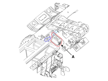
| 3. |
Disconnect the connector of the immobilizer unit and then remove the immobilizer unit (A) after loosening a bolt.
|
| Installation |
| 1. |
Install the immobilizer control unit after connecting the unit connector. |
| 2. |
Install the main crash pad assembly. |
| 3. |
Connect the negative (-) battery terminal. |
Schematic diagrams Circuit Diaram Description and operation Description The immobilizer system will disable the vehicle unless the proper ignition key is used, in addition to the currently available anti-theft systems such as car alarms, the immobilizer system aims to drastically reduce the rate of auto theft.
Repair procedures Removal 1. Disconnect the negative (-) battery terminal. 2. Remove the crash pad lower panel.
Other information:
Kia Rio 2017-2023 YB Service Manual: Rear Wiper Motor
Repair procedures Inspection Rear Wiper Motor 1. Remove the connector from the rear wiper motor. 2. Connect positive (+) battery cables to terminal 4 and negative (-) battery cables to terminal 3 respectively.
Kia Rio 2017-2023 YB Service Manual: Smart Key Diagnostic
Repair procedures Inspection Self Diagnosis With Scan Tool It will be able to diagnose defects of SMART KEY system with KDS/GDS quickly. KDS/GDS can operates actuator forcefully, input/output value monitoring and self diagnosis. The following three features will be major problem in SMART KEY system.
Categories
- Manuals Home
- Kia Rio Owners Manual
- Kia Rio Service Manual
- Motor Driven Power Steering
- Cooling System
- Filler-Neck Assembly
- New on site
- Most important about car
