
Kia Rio: Clutch System / Ignition Lock Switch
Specifications
| Specifications |
|
Item |
Specifications |
|
Working voltage |
DC 12.5V |
|
Operating force |
Initial position : 0.25 ± 0.15N(0.025 ± 0.015kg, 0.056 ± 0.034lb) |
|
Full position : 0.8 ± 0.2 N(0.08 ± 0.02 kgf, 0.579 ± 0.014 lb-ft) |
|
|
Working temperature |
-40°C to 80°C (-40°F to 176°F) |
Description and operation
| Description |
| – |
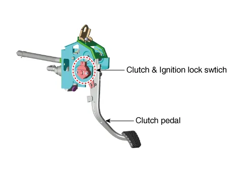
Ignition lock switch is mounted on the clutch pedal. |
| – |
Ignition lock switch is operated when you press the clutch pedal. |
| – |
If the clutch pedal is not pressed down, the engine is not started. |
Repair procedures
| Inspection |
Component Inspection
| 1. |
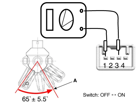
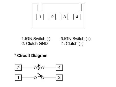
Remove the clutch & ignition lock switch. |
| 2. |
Rotate the switch lever to the direction of the arrow to check the operating point (A).
|
| Removal |
| 1. |
Turn ignition switch OFF and disconnect the negative (-) battery cable. |
| 2. |
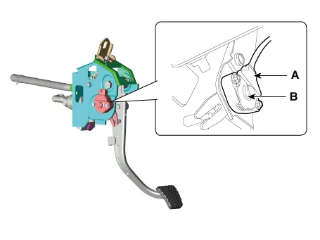
Disconnect the ignition lock switch connector (A). |
| 3. |
Remove the ignition lock and clutch switch (B).
|
| Installation |
| 1. |
Install in the reverse order of removal.
|


Components and components location Components 1. Clutch release fork 2. Clutch cover assembly 3. Clutch disk assembly 4.
Specifications Specifications Item Specifications Working voltage DC 12.5V Operating force Initial position : 0.
Other information:
Kia Rio 2017-2023 YB Service Manual: Front Washer Motor
Repair procedures Inspection Front Washer Motor 1. With the washer motor connected to the reservoir tank, fill the reservoir tank with water. • Before filling the reservoir tank wi
Kia Rio 2017-2023 YB Service Manual: Heating,Ventilation, Air Conditioning
Specifications Specification Air Conditioner Item Specification Compressor Type DVE12 Oil type & Capacity PAG 30, 120 ± 10 g Displacement 122 cc/rev Expansion valve Type
Categories
- Manuals Home
- Kia Rio Owners Manual
- Kia Rio Service Manual
- Clutch System
- Maintenance
- Engine Control / Fuel System
- New on site
- Most important about car
