Kia Rio: Crash Pad / Glove Box Housing
Components and components location
| Component Location |
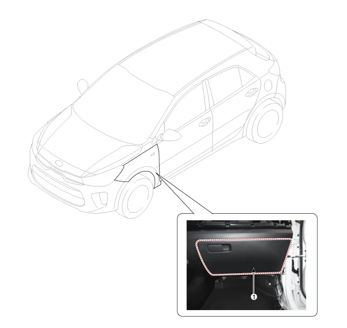
| 1. Glove box housing assembly
|
Repair procedures
| Replacement |
Put on gloves to protect your hands. |

|

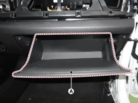
| 1. |
Disconnect the stopper (B) from the glove box (A).
|
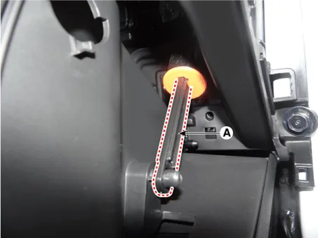
| 2. |
Disconnect the air damper (A) from the glove box.
|
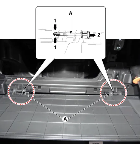
| 3. |
Disconnect the pins (A) and then remove the glove box (B).
|
| 4. |
Install in the reverse order of removal.
|
Components and components location Component Location 1. Crash pad lower panel Repair procedures Replacement Put on gloves to protect your hands.
Components and components location Component Location 1. Steering column shroud lower panel 2. Steering column shroud upper panel Repair procedures Replacement [Steering column shroud upper panel] Put on gloves to protect your hands.
Other information:
Kia Rio 2017-2023 YB Service Manual: Keyless Entry And Burglar Alarm
Specifications Specification Item Specification Power source 3 V Operating temperature -22 - 176°F (-30 - 80°C) RF Modulation FSK LF Modulation ASK RF frequency
Kia Rio 2017-2023 YB Service Manual: Windshield Wiper-Washer Switch
Repair procedures Removal [BCM Type] 1. Disconnect the negative (-) battery terminal. 2. Remove the steering wheel. (Refer to Steering System - "Steering Wheel") 3.
Categories
- Manuals Home
- Kia Rio Owners Manual
- Kia Rio Service Manual
- Cooling System
- Engine Oil and Filter
- Clutch System
- New on site
- Most important about car
