Kia Rio: Fuel Delivery System / Fuel Pump
Repair procedures
| Inspection |
[Fuel pump]
| 1. |
Turn ignition switch OFF and disconnect the negative (-)battery cable. |
| 2. |
Remove the fuel pump assembly. |
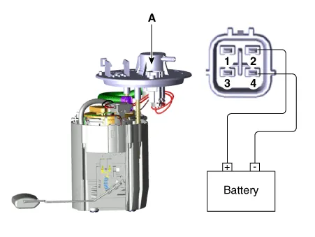
| 3. |
Check motor operation by fuel pump connector (A) connecting power(No.2) and ground(No.4)
|
[Fuel sender]
| 1. |
Using an ohmmeter, measure the resistance between terminals 1 and 3 of sender connector (A) at each float level.
|
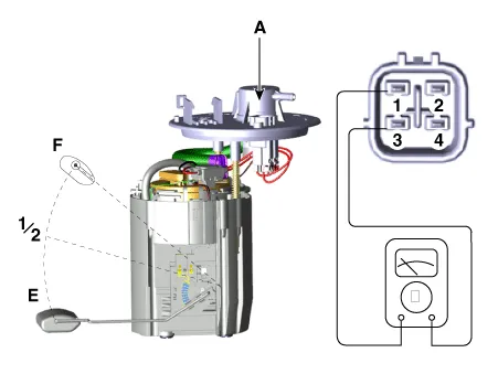
| 2. |
Also, check that the resistance changes smoothly when the float moves from "E" to "F".
|
| Removal |
| 1. |
Release the residual pressure in fuel line. (Refer to Delivery System - “Release Residual Pressure in Fuel Line”) |
| 2. |
Remove the rear seat. (Refer to Body - "Rear Seat Assembly") |
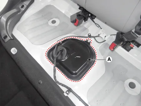
| 3. |
Remove the fuel pump service cover (A).
|
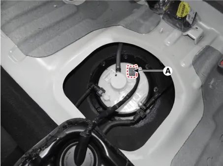
| 4. |
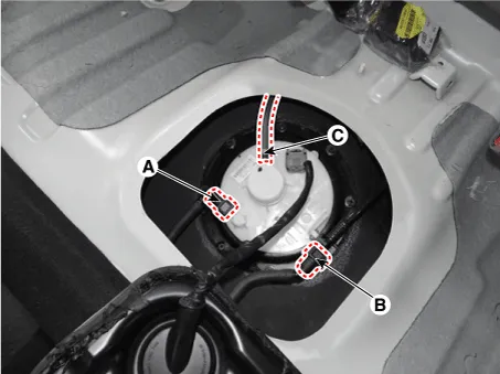
Disconnect the fuel pump connector (A).
|
| 5. |
Disconnect the fuel feed tube quick-connector (A), the vapor tube quick-connector (B) and the vapor hose (C).
|
| 6. |
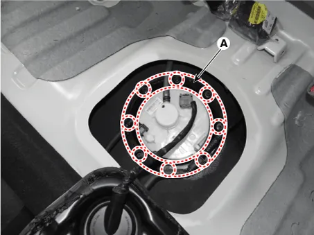
Remove the plate cover (A) after removing the installation bolts and then remove the fuel pump from the fuel tank.
|
| Installation |
| 1. |
Installation is reverse of removal.
|

Repair procedures Removal 1. Release the residual pressure in fuel line. (Refer to Delivery System - "Release Residual Pressure in Fuel Line”) 2.
Repair procedures Removal 1. Remove the fuel pump. (Refer to Fuel Delivery System - "Fuel Pump") 2.
Other information:
Kia Rio 2017-2023 YB Service Manual: Power Windows
Components and components location Component Location 1. Driver power window switch 2. Assist power window switch 3. Rear power window switch 4. Front window motor 5. Rear window motor Description and operation Safety Function of Power Window When driver door power win
Kia Rio 2017-2023 YB Service Manual: Intake Actuator
Description and operation Description The intake actuator is located at the blower unit. It regulates the intake door by signal from control unit. Pressing the intake selection switch will shift between recirculation and fresh air modes.
Categories
- Manuals Home
- Kia Rio Owners Manual
- Kia Rio Service Manual
- Body (Interior and Exterior)
- Engine Mechanical System
- Cooling System
- New on site
- Most important about car
