
Kia Rio: Front Suspension System / Front Strut Assembly
Components and components location
| Components Location |

| 1. Lock nut 2. Insulator dust cap 3. Self lock nut 4. Strut insulator 5. Strut bearing 6. Spring upper seat |
7. Spring upper pad 8. Coli spring 9. Dust cover 10. Bumper rubber 11. Spring lower pad 12. Shock absorber |
Repair procedures
| Removal |
| 1. |
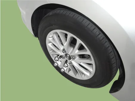
Remove wheel nuts, front wheel and tire from front hub.
|

| 2. |
Remove the cowl top cover. (Refer to Body - "Cowl Top Cover") |
| 3. |
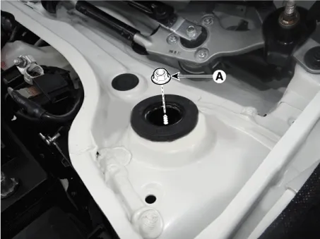
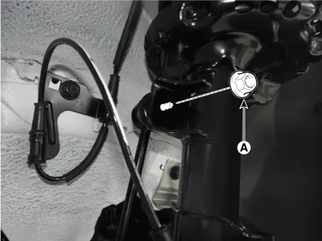
Remove the strut lock nuts (A).
|
| 4. |
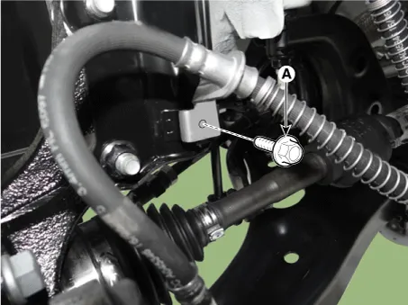
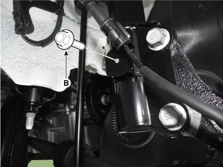
Remove the brake caliper hose bracket bolt (A) and wheel speed sensor bracket bolt (B).
|
| 5. |
Remove the stabilizer link nut (A).
|

| 6. |
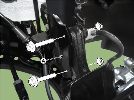
Loosen the bolts and then remove the strut assembly (A) from the knuckle.
|
| 7. |
Install in the reverse order of removal. |
| Disassembly |
| 1. |
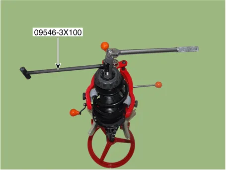
Using a strut spring compressor, compress the coil spring.
|
| 2. |
Using the SST (09546-3X100), loosen the self locking nut.
|
| 3. |
Remove the insulator, spring seat, coil spring and dust cover from the strut assembly. |
| 4. |
Reassembly is the reverse of the disassembly. |
| Inspection |
| 1. |
Check the strut insulator for wear or damage. |
| 2. |
Check rubber parts for damage or deterioration. |
| 3. |
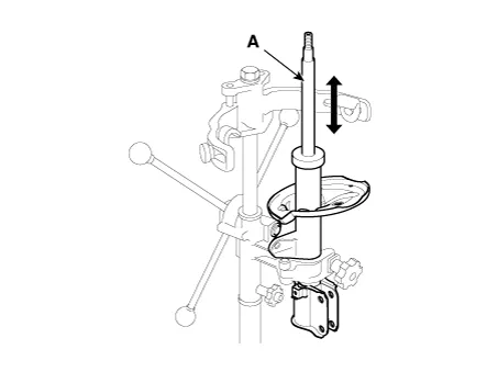
Compress and extend the piston rod (A) and check that there is no abnormal resistance or unusual sound during operation.
|
Disposal
| 1. |
Fully extend the piston rod. |
| 2. |
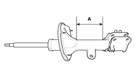
Drill a hole on the A section to remove gas from the cylinder.
|
Components and components location Components Location 1. Gear box 2. Stabilizer bar 3. Driveshaft 4. Stabilizer link 5.
Repair procedures Removal 1. Remove wheel nuts, front wheel and tire from front hub. Tightening torque: 107.
Other information:
Kia Rio 2017-2023 YB Service Manual: Photo Sensor (FATC only)
Description and operation Description The photo sensor is located at the center of defrost nozzles. The photo sensor contains a photovoltaic (sensitive to sunlight) diode. The solar radiation received by its light receiving portion, generates an electromotive force in proportion to the amount of radiation received which is tran
Kia Rio 2017-2023 YB Service Manual: Mode Control Actuator
Description and operation Description The mode control actuator is located at the heater unit. It adjusts position of mode door by operating mode control actuator based on signal of A/C control unit. Pressing mode select switch makes the mode control actuator shift in order of Vent → Bi-Level → Floor → Mix.
Categories
- Manuals Home
- Kia Rio Owners Manual
- Kia Rio Service Manual
- Engine Control / Fuel System
- Fuse/relay panel description
- Maintenance
- New on site
- Most important about car
