Kia Rio: Brake System / ESC (Electronic Stability Control) System
Components and components location
| Components |
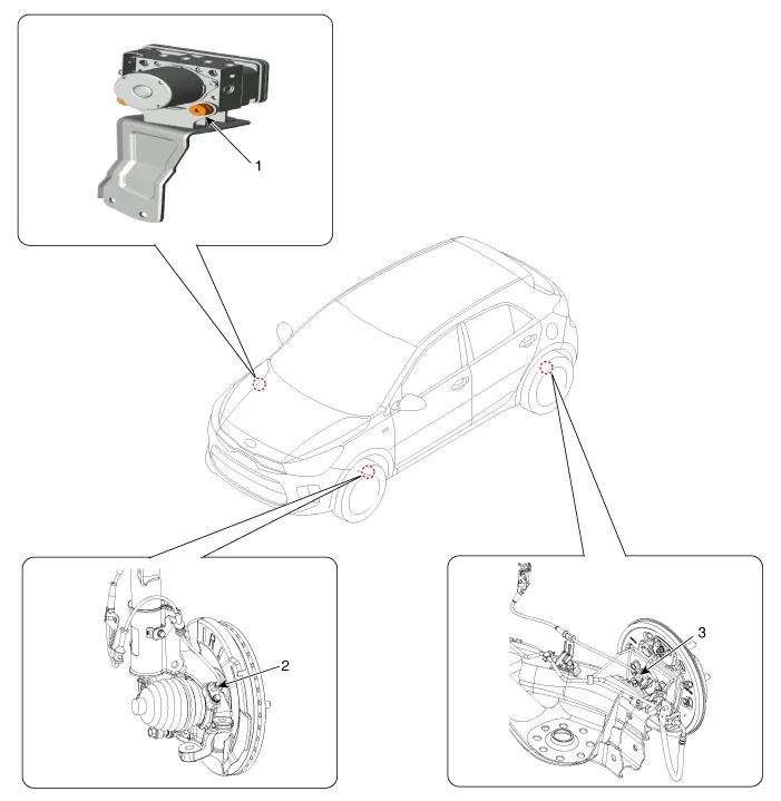
| 1. ESC control module 2. Front wheel speed sensor |
3. Rear wheel speed sensor
|
Description and operation
| Description of ESC |
Electronic Stability Control (ESC) recognizes critical driving conditions, such as panic reactions in dangerous situations, and stabilizes the vehicle by wheel-individual braking and engine control intervention.
ESC adds an additional function known as Active Yaw Control (AYC) to the ABS, TCS, EBD and ESC functions. On contrary, the ABS/TCS function controls wheel slip during braking and accelerating, and thus, mainly intervenes in the longitudinal dynamics of the vehicle, and the active yaw control stabilizes the vehicle on the vertical axis.
This is achieved by wheel individual brake intervention and adaptation of the momentary engine torque with no need for any action to be taken by the driver.
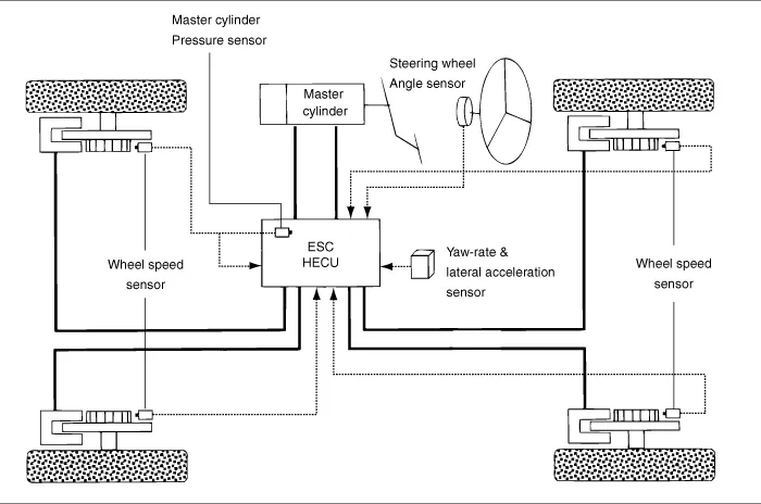
ESC essentially consists of three assemblies : the sensors, the electronic control unit and the actuators.
The stability control feature works under all driving and operating conditions. Under certain driving conditions, the ABS/TCS function can be activated simultaneously with the ESC function in response to a command by the driver.
In the event of a failure of the stability control function, the basic safety function, ABS, is still maintained.

Description of ESC Control
ESC system consists of ABS/EBD, TCS and AYC functions.
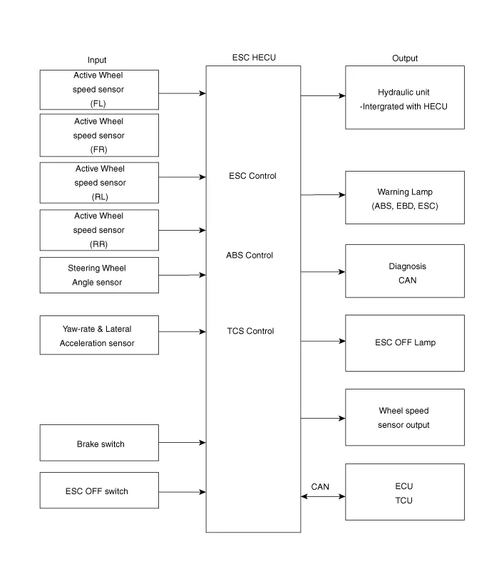
ABS/EBD function : The ECU changes the active sensor signal (current shift) coming from the four wheel sensors into square waves. By using the input of above signals, the ECU calculates the vehicle speed and the acceleration & deceleration of the four wheels. And, the ECU judges whether the ABS/EBD should be actuated or not.
TCS function prevents the wheel slip of drive direction by adding the brake pressure and engine torque reduction via CAN communication. TCS function uses the wheel speed sensor signal to determine the wheel slip as far as ABS function.
AYC function prevents unstable maneuver of the vehicle. To determine the vehicle maneuver, AYC function uses the maneuver sensor signals (Yaw Rate Sensor, Lateral Acceleration Sensor, and Steering Wheel Angle Sensor).
If vehicle maneuver is unstable (Over Steer or Under Steer), AYC function applies the brake pressure on certain wheel, and sends engine torque reduction signal by CAN.
After the key-on, the ECU continuously diagnoses the system failure (self-diagnosis). If the system failure is detected, the ECU informs driver of the system failure through the BRAKE/ABS/ESC warning lamp (fail-safe warning).
Input and Output Diagram
| ESC Operation Mode |
| ESC Hydraulic System Diagram |

| 1. |
ESC Non-operation : Normal braking.
|
| 2. |
ESC operation
|
||||||||||||||||||||||
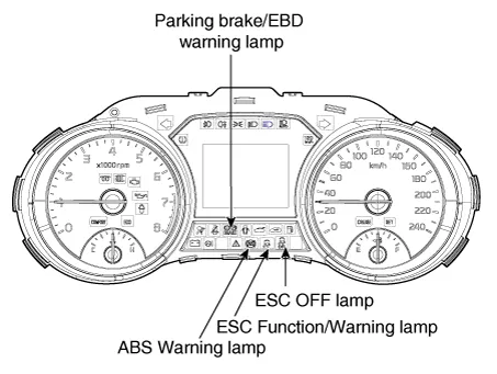
ABS Warning Lamp module
The active ABS warning lamp module indicates the self-test and failure status of the ABS. The ABS warning lamp is turned on under the following conditions:
| – |
During the initialization phase after IGN ON. (continuously 3 seconds). |
| – |
In the event of inhibition of ABS functions by failure. |
| – |
During diagnostic mode. |
| – |
When the ECU Connector is seperated from ECU. |
| – |
Cluster lamp is ON when communication is impossible with CAN module. |
EBD/Parking Brake Warning Lamp Module
The active EBD warning lamp module indicates the self-test and failure status of the EBD. However, in case the Parking Brake Switch is turned on, the EBD warning lamp is always turned on regardless of EBD functions. The EBD warning lamp is turned on under the following conditions:
| – |
During the initialization phase after IGN ON. (continuously 3 seconds). |
| – |
When the Parking Brake Switch is ON or brake fluid level is low. |
| – |
When the EBD function is out of order . |
| – |
During diagnostic mode. |
| – |
When the ECU Connector is seperated from ECU. |
| – |
Cluster lamp is ON when communication is impossible with CAN module. |
ESC Function/Warning Lamp
The ESC function/warning lamp indicates the self-test and failure status of the ESC.
The ESC function/warning lamp is turned on under the following conditions:
| – |
During the initialization phase after IGN ON. (continuously 3 seconds). |
| – |
When the ESC function is inhibited by system failure. |
| – |
When the ESC control is operating. (Blinking - 2Hz) |
| – |
During diagnostic mode.(Except standard mode) |
| – |
Cluster lamp is ON when communication is impossible with CAN module. |
ESC Off Lamp
The ESC Off lamp indicates the self-test and operating status of the ESC.
The ESC Off lamp operates under the following conditions :
| – |
During the initialization mode after IGN ON. (continuously 3 seconds). |
| – |
ESC Off lamp is On when driver input the ESC Off switch. |
ESC On/Off Switch
The ESC On/Off Switch is used to toggle the ESC function between On/Off states based upon driver input.
The On/Off switch is a normally open, momentary contact switch. Closed contacts switch the circuit to ignition.
Initial status of the ESC function is on and switch toggle state.
Schematic diagrams
| Schemaitc Diagrams |
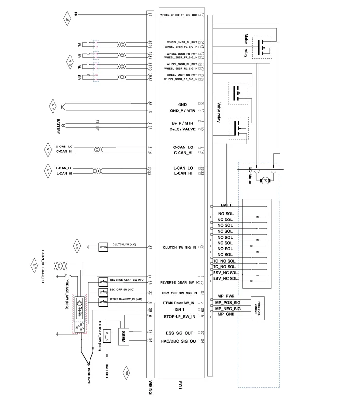
| Terminal Function |
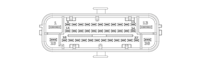
|
Pin No |
Description |
Current |
Resistance |
Remark |
|
(AMPS) |
(mΩ) |
|||
|
1 |
B+ PUMP MOTOR POWER |
137(RUSH) |
10 |
|
|
2 |
C-CAN Low |
30 mA |
250 |
|
|
5 |
ITPMS Reset Switch Inout |
10mA |
250 |
|
|
11 |
PARKING BRAKE SWITCH SIGNAL |
10mA |
250 |
|
|
13 |
GND_PUMP MOTOR GROUND |
137(RUSH) |
10 |
|
|
14 |
C-CAN High |
30 mA |
250 |
|
|
16 |
BRAKE LIGHT SWITCH SIGNAL |
10 mA |
250 |
|
|
17 |
WHEEL SPEED OUTPUT (FR) |
16mA |
250 |
|
|
18 |
WHEEL SPEED SENSOR POWER (FR) |
30 mA |
250 |
|
|
19 |
WHEEL SPEED SENSOR POWER (RR) |
30 mA |
250 |
|
|
20 |
WHEEL SPEED SENSOR SIGNAL GROUND (RL) |
16.8 mA |
250 |
|
|
21 |
WHEEL SPEED SENSOR SIGNAL GROUND (FL) |
16.8 mA |
250 |
|
|
22 |
L-CAN HIGH |
30 mA |
250 |
|
|
23 |
ESC ON/OFF SWITCH SIGNAL |
10 mA |
250 |
|
|
24 |
HAC DRIVE SIGNAL |
200 mA |
250 |
|
|
25 |
BATTERTY(+) SOLENOID |
40 |
10 |
|
|
27 |
ESS DRIVE SIGNAL |
200mA |
250 |
|
|
29 |
IGNITION1 |
50mA |
60 |
|
|
31 |
WHEEL SPEED SENSOR SIGNAL GROUND (FR) |
16.8mA |
250 |
|
|
32 |
WHEEL SPEED SENSOR SIGNAL GROUND (RR) |
16.8mA |
250 |
|
|
33 |
WHEEL SPEED SENSOR POWER (RL) |
30mA |
250 |
|
|
34 |
WHEEL SPEED SENSOR POWER (FL) |
30 mA |
250 |
|
|
35 |
L-CAN LOW |
30 mA |
250 |
|
|
36 |
REVERSE GEAR SWITCH SIGNAL |
10mA |
250 |
|
|
37 |
CLUTCH SWITCH SIGNAL |
10 mA |
250 |
|
|
38 |
GROUND |
40 |
10 |
|
- ESC Control Module
- Front Wheel Speed Sensor
- Rear Wheel Speed Sensor
- ESC OFF Switch
- Emergency Signal System
Components and components location Components Drum type Disc type Repair procedures Removal 1. Remove the rear wheel & tire.
Components and components location Components 1. ESC control module connector 2. ESC control module 3. ESC bracket Repair procedures Removal 1.
Other information:
Kia Rio 2017-2023 YB Service Manual: Immobilizer System
Schematic diagrams Circuit Diaram Description and operation Description The immobilizer system will disable the vehicle unless the proper ignition key is used, in addition to the currently available anti-theft systems such as car alarms, the immobilizer system aims to drastically reduce the rate of auto theft.
Kia Rio 2017-2023 YB Service Manual: Smart Key System
Specifications Specifications Smart Key Unit Items Specification Rated voltage DC 12 V Operating voltage DC 9 - 16 V Operating temperature -31 - 167°F (-35 - 75°C) Load Max.
Categories
- Manuals Home
- Kia Rio Owners Manual
- Kia Rio Service Manual
- Brake System
- Maintenance
- Coolant
- New on site
- Most important about car
