
Kia Rio: ESC (Electronic Stability Control) System / Emergency Signal System
Description and operation
| Description |
Introduction of quick brake warning system (ESS)
In case of quick brake by driver, the brake lamp or turn signal is blinked to warn against the vehicle at rear.

| 1. |
Basic function (Blinking the brake lamp/emergency lamp)
|
| 2. |
Additional function (Blinking the turn signal)
|

System configuration

ESS Circuit diagram
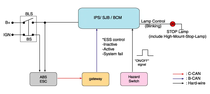
Description and operation Description 1. The ESC OFF switch is for the user to turn off the ESC system. 2.
Description and operation Description – AEB system is designed to help avoid a potential collision or reduce its impact when drivers applies inadequate, delayed or no brakes at all to avoid a collision.
Other information:
Kia Rio 2017-2023 YB Service Manual: Intake Actuator
Description and operation Description The intake actuator is located at the blower unit. It regulates the intake door by signal from control unit. Pressing the intake selection switch will shift between recirculation and fresh air modes.
Kia Rio 2017-2023 YB Service Manual: Heater & A/C Control Unit (FATC)
Components and components location Components Connector Pin Function No. Connector A Connector B 1 Battery ⁻ 2 ISG battery (+) ⁻ 3 Illumination (+) ⁻
Categories
- Manuals Home
- Kia Rio Owners Manual
- Kia Rio Service Manual
- Filler-Neck Assembly
- Body Electrical System
- Restraint
- New on site
- Most important about car
