Kia Rio: Engine And Transaxle Assembly / Engine Cover
Repair procedures
| Removal and Installation |
| 1. |
Remove the engine cover (A).
|
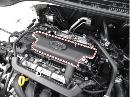
| 2. |
Install in the reverse order of removal. |
Repair procedures Removal and Installation 1. Remove the engine room under cover (A). Tightening torque : 7.
Other information:
Kia Rio 2017-2023 YB Service Manual: Hazard Lamp Switch
Repair procedures Inspection 1. Check for continuity between terminals. If the continuity is not as specified, replace the hazard lamp switch. No. Description No.
Kia Rio 2017-2023 YB Service Manual: Rear Wiper Motor
Repair procedures Inspection Rear Wiper Motor 1. Remove the connector from the rear wiper motor. 2. Connect positive (+) battery cables to terminal 4 and negative (-) battery cables to terminal 3 respectively.
Categories
- Manuals Home
- Kia Rio Owners Manual
- Kia Rio Service Manual
- Maintenance
- Suspension System
- Filler-Neck Assembly
- New on site
- Most important about car
