
Kia Rio: Drive Belt System / Drive Belt
Repair procedures
| Removal and Installation |
| 1. |
Remove the engine room under cover. (Refer to Engine and Transaxle Assembly - "Engine Room Under Cover") |
| 2. |
Remove the drive belt.
|
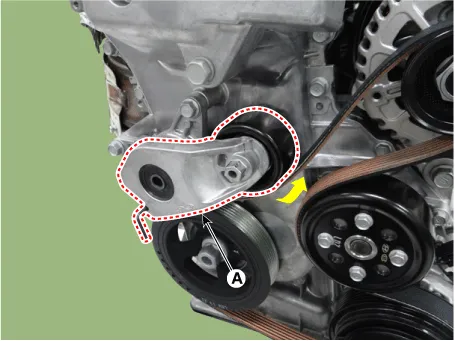
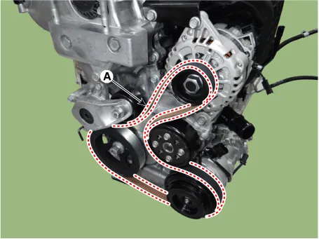
| 3. |
Install in the reverse order of removal. |
| Inspection |
| Drive Belt Inspection |
| 1. |
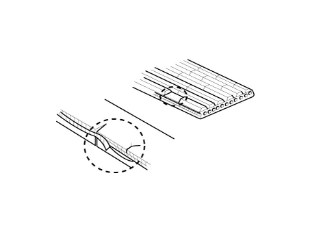
Visually check the belt for excessive wear, frayed cords etc. If any defect has been found, replace the drive belt.
|

| 2. |
Check belt for maintenance and abnormal wear of V-ribbed part. Replace if necessary.
|
Repair procedures Removal and Installation 1. Remove the engine room under cover. (Refer to Engine and Transaxle Assembly - "Engine Room Under Cover") 2.
Other information:
Kia Rio 2017-2023 YB Service Manual: Ignition Switch
Repair procedures Inspection 1. Disconnect the key warning switch connector (A) and ignition switch connector (B) from the steering column. 2. Check for continuity between the terminals.
Kia Rio 2017-2023 YB Service Manual: Smart Key System
Specifications Specifications Smart Key Unit Items Specification Rated voltage DC 12 V Operating voltage DC 9 - 16 V Operating temperature -31 - 167°F (-35 - 75°C) Load Max.
Categories
- Manuals Home
- Kia Rio Owners Manual
- Kia Rio Service Manual
- CVVT & Camshaft
- Maintenance
- Clutch System
- New on site
- Most important about car
