Kia Rio: Manual Transaxle Control System / Control Cable
Components and components location
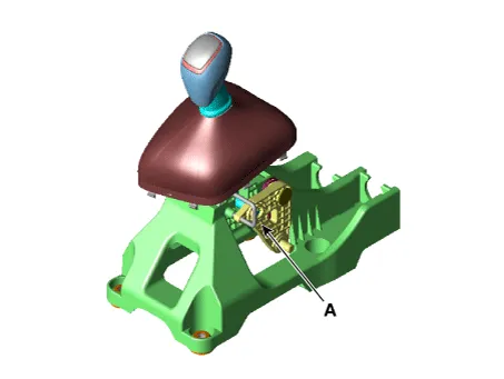
| Components |
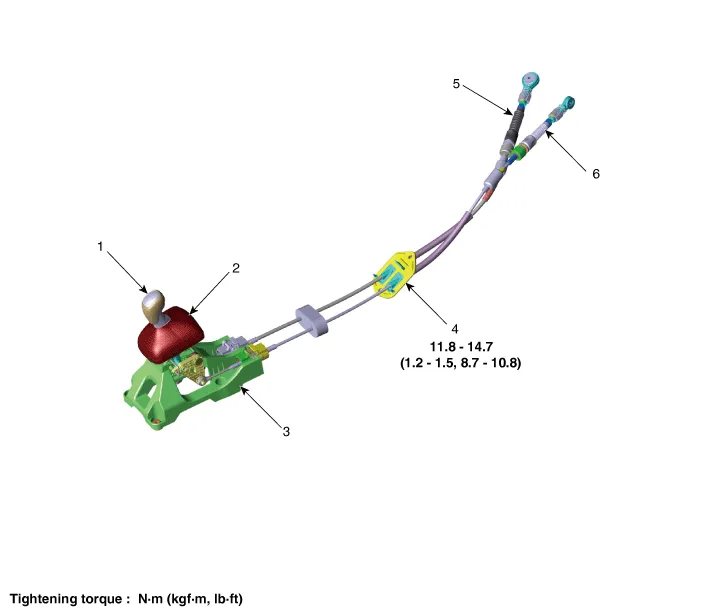
|
1. Knob 2. boots 3. Shift lever assembly |
4. Retainer 5. Shift cable 6. Select cable |
Repair procedures
| Removal |
| 1. |
Move the shift lever to 4th gear. |
| 2. |
Remove the air cleaner assembly. (Refer to Engine Mechanical System - "Air Cleaner") |
| 3. |
Remove the battery and battery tray. (Refer to Engine Electrical System - "Battery") |
| 4. |
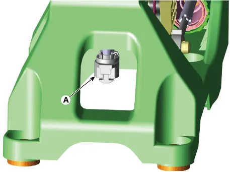
Remove the control cable.
|

| 5. |
Remove the floor console assembly. (Refer to Body - " Floor Console Assembly") |
| 6. |
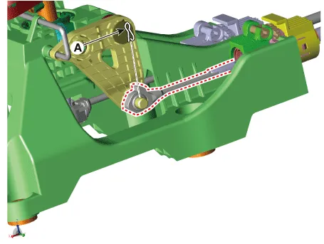
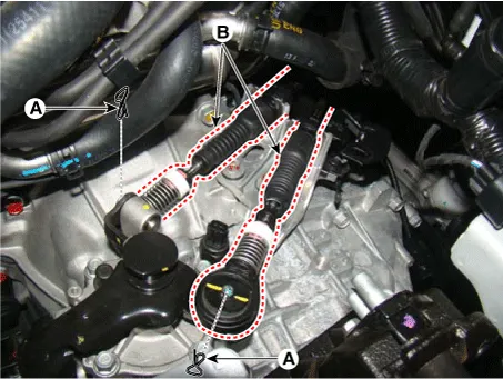
Remove the snap pin (A) and then remove the select cable from the shift lever pin.
|
| 7. |
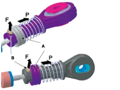
Remove the shift cable (A). [A Type]
[B Type]
|

| 8. |
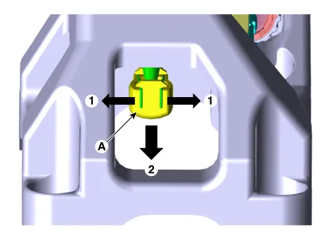
Remove the cable sockets (A) from the shift lever.
|

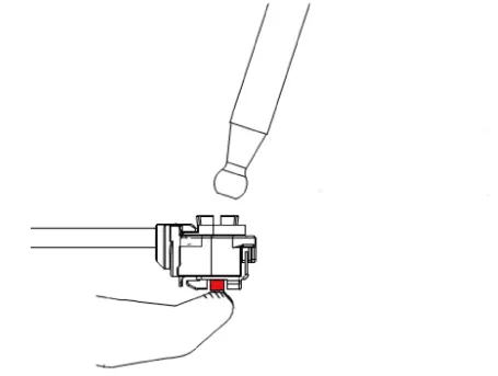
| 9. |
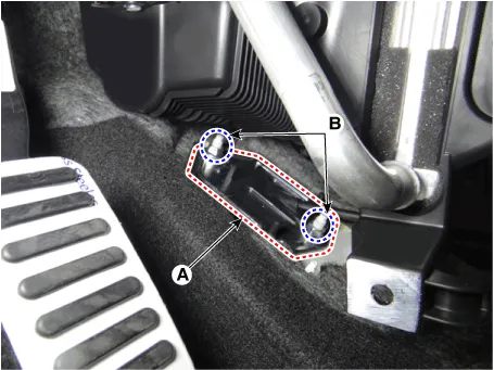
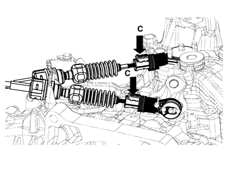
Remove the shift cable retainer (A) after loosening the nuts (B). Then, remove the shift cable by pulling it toward the vehicle interior.
|
| Installation |
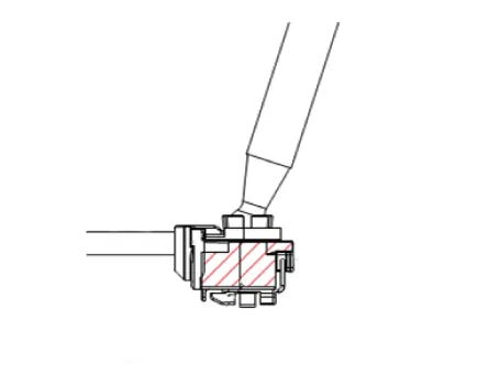
| 1. |
Install the shift cable retainer (A) by tightening nuts (B).
|
| 2. |
Install the cable sockets (A).
|

| 3. |
Install the shift cable (A). [A Type]
[B Type]
|


| 4. |
Install the select cable to the lever pin and then insert the snap pin (A).
|
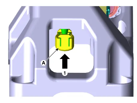
| 5. |
Check that the shift lever and control shaft are placed in the "4th" position and then install the 4th fixing pin (A).
|
| 6. |
Install the control cable.
|
| 7. |
Check for proper operation of control shaft lever when operated (1st, 2nd, 3rd, 4th, 5th, 6th, R gear). |
| 8. |
Install the battery and battery tray. (Refer to Engine Electrical System - "Battery") |
| 9. |
Install the air cleaner assembly. (Refer to Engine Mechanical System - "Air Cleaner") |
| 10. |
Install the floor console assembly. (Refer to Body - "Floor Console Assembly") |
Components and components location Components 1. Knob 2. boots 3. Shift lever assembly 4. Retainer 5.
Other information:
Kia Rio 2017-2023 YB Service Manual: Rear Glass Defogger Printed Heater
Repair procedures Inspection • Wrap tin foil around the end of the voltmeter test lead to prevent damaging the heater line. Apply pressure on the tin foil with hand and move the tin foil along the grid line to check for open circ
Kia Rio 2017-2023 YB Service Manual: Rear Washer Motor
Repair procedures Inspection 1. With the washer motor connected to the reservoir tank, fill the reservoir tank with water. Before filling the reservoir tank with water, check the filter for foreign material or conta
Categories
- Manuals Home
- Kia Rio Owners Manual
- Kia Rio Service Manual
- Engine Oil and Filter
- Engine Control / Fuel System
- Maintenance
- New on site
- Most important about car
