Kia Rio: Clutch System / Clutch Release Cylinder
Components and components location
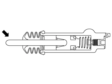
| Components |
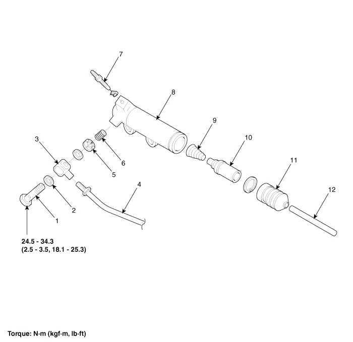
| 1. Union bolt 2. Gasket 3. Tube joint 4. Clutch tube 5. Valve plate 6. Valve spring |
7. Bleeder screw 8. Release cylinder 9. Return spring 10. Piston 11. Boot 12. Push rod |
Repair procedures
| Removal |
[Gasoline 1.2]
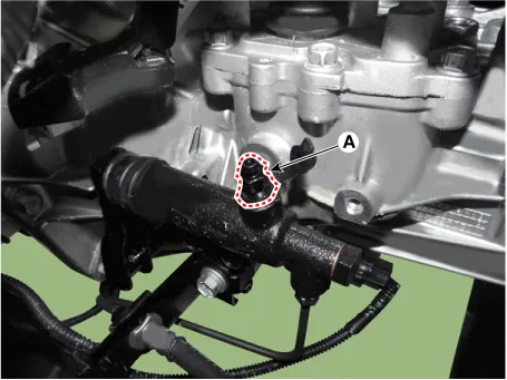
| 1. |
Drain the brake fluid through the bleed plug (A).
|

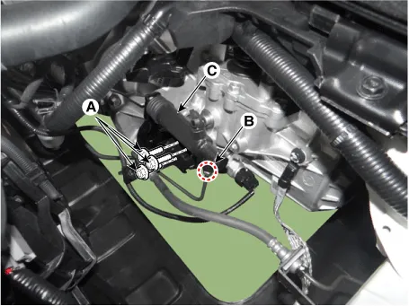
| 2. |
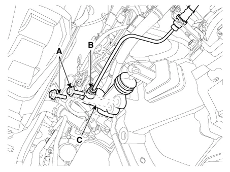
Loosen the release cylinder bolts (A) and then clutch tube nut (B) after removing release cylinder assembly (C ).
|
[Gasoline 1.0 T-GDI, 1.4, Diesel 1.4]
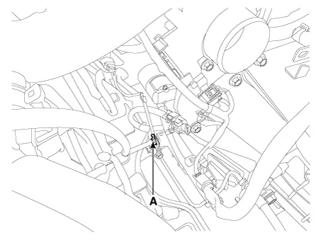
| 1. |
Drain the brake fluid through the bleed plug (A).
|
| 2. |
Loosen the release cylinder bolts (A) and then clutch tube nut (B) after removing release cylinder assembly ©.
|
| Installation |
| 1. |
Install in the reverse order of removal.
|
| Inspection |
| 1. |
Check the clutch release cylinder for fluid leakage. |
| 2. |
Check the clutch release cylinder boot for damage. |
| Adjustment |
Clutch Release Cylinder Air Bleeding Procedure
Use the specified fluid. Avoid mixing different brands of fluid. |
| 1. |
After disconnecting a cap from the clutch release cylinder air bleeder, insert a vinyl hose in the plug. |
| 2. |
Refill the clutch master cylinder with the specified fluid.
|
| 3. |
Loosening the plug screw, press and release the clutch pedal about 10 times. |
| 4. |
Tighten the plug (A) during the clutch pedal pressed. Afterwards, raise the pedal with a hand. |
| 5. |
After pressing the clutch pedal 3 times more, loosen the plug (A) and re-tighten it with the pedal pressed. Raise it again, then.
|
| 6. |
Repeat the step 4 two or three times. (until there is no bubble in the fluid) [Gasoline 1.2]
[Gasoline 1.0 T-GDI, 1.4, Diesel 1.4]
|
| 7. |
Refill the clutch master cylinder with the specified fluid. |
Components and components location Components [Gasoline 1.2, 1.4] 1. Clutch pedal assembly 2. Ignition lock and clutch switch 3.
Components and components location Components 1. Clutch release fork 2. Clutch cover assembly 3. Clutch disk assembly 4.
Other information:
Kia Rio 2017-2023 YB Service Manual: Power Door Lock Module
Components and components location Components 1. Door lock/unlock knob cable 2. Door latch assembly Repair procedures Inspection • When removing with a flat-tip screwdriver or remover, wrap
Kia Rio 2017-2023 YB Service Manual: Sunroof
C
Categories
- Manuals Home
- Kia Rio Owners Manual
- Kia Rio Service Manual
- Motor Driven Power Steering
- General Information
- CVVT & Camshaft
- New on site
- Most important about car
