Kia Rio: Brake System / Assist Emergency Braking(AEB) System
Description and operation
| Description |
| – |
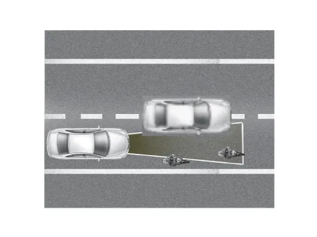
AEB system is designed to help avoid a potential collision or reduce its impact when drivers applies inadequate, delayed or no brakes at all to avoid a collision. |
| – |
The system detects the risk factors on the road by using the frontal impact sensor and warn the driver and activate the emergency brake to prevent collision or reduce collision speed. |
The following is the system control process
| 1. |
Confirm the object to be protected by AEB system (vehicles and pedestrians) by using the analyzed data. |
| 2. |
Calculate the speed reduction depending on the speed, distance, existence or nonexistence of preceding vehicle. |
| 3. |
Report the "required speed reduction" to Electronic Stability Control (ESC) (CAN Comm.) |
| 4. |
ESC performs automatic control after calculating the required torque to achieve "required speed reduction" (CAN Comm.). |
| Operation |
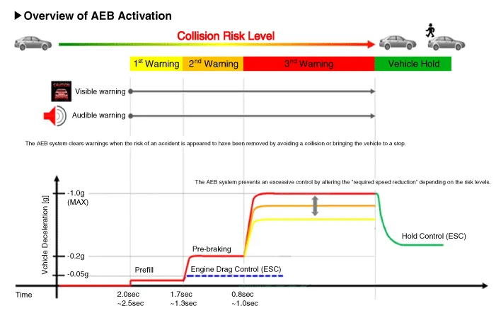
※ The time indicated will be changed according to vehicle speeds.
| • |
Step 1: Issue a visual (display) and vocal alarm when a danger is detected. |
| • |
Step 2: Reduce engine torque and activates AEB when there is a high chance of collision. |
| • |
Step 3: Activate emergency brake when a collision is imminent. |
| • |
After stopping the vehicle: Maintain the braking control for a certain time and then release it. |
|

|

|

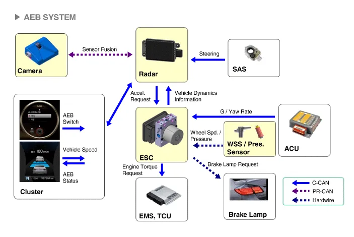
Components and components location
| Components |
The following is the configuration of the AEB system.
| – |
Detection device (radar and camera) that can recognize potential obstacles in the front. |
| – |
Human-Machine Interface (HMI) to warn driver or change settings. |
| – |
Braking system to automatically brake the car |
Schematic diagrams
| Schematic diagram |
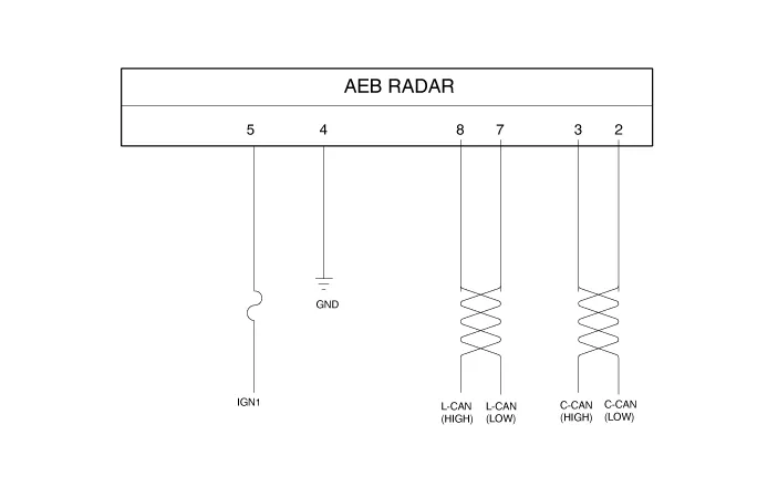
| Terminal Function |

|
NO. |
Terminal function |
|
1 |
- |
|
2 |
C-CAN LOW |
|
3 |
C-CAN HIGH |
|
4 |
GND |
|
5 |
IGN1 |
|
6 |
- |
|
7 |
L-CAN_LO |
|
8 |
L-CAN_HI |
Repair procedures
| Inspection |
AEB function ON / OFF switch was included to USM (User Setting Menu) and the state of the factory is ON.
When the IGN On, maintain ON condition by default. And does not reflect the driver settings when next IGN On.
If turned the ESC function Off, the AEB function is turned off.
| – |
The ON/OFF for AEB is included in the USM (User Setting Menu) and the default is ON. |
| – |
While IGN is On, it stays at ON, however, the driver's settings do not last next time when IGN is newly On. |
| – |
When ESC is Off, AEB is also turned Off. |
| Removal |
| 1. |
Turn the ignition switch off and disconnect the battery (-) terminal. |
| 2. |
Remove the front bumper cover. (Refer to the Body - "Front Bumper Assembly") |
| 3. |
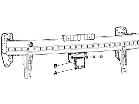
Disconnect the AEB ladar connector (A) and then remove the AEB radar unit (B).
|
LDWS camera
AEB, contrary to SCC (Smart Cruise Control) has to work on a stationary car so the system uses the Fusion Target system to combine radar and camera.
| 1. |
Disconnect the battery (-) cable. |
| 2. |
Remove the camera. (Refer to Body Electrical System - "Lane Departure Warning System (LDWS) Unit") |
| Installation |
AEB radar
| 1. |
Installation is the reverse of removal. |
| 2. |
Perform AEB variant coding |
| 3. |
Perform the AEB radar alignment. |
LDWS camera
| 1. |
Installation is the reverse of removal. |
| 2. |
Perform Service Point Target Auto Calibration (SPTAC). (Refer to Body Electrical System - "Lane Departure Warning System (LDWS)") |
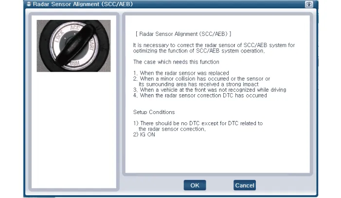
| Assist Emergency Braking (AEB) Radar Sensor Alignment |
AEB system is designed to help avoid a potential collision or reduce its impact when drivers applies inadequate, delayed or no brakes at all to avoid a collision.
In order for the radar sensor to operate correctly, it must be properly aligned parallel to the driving direction of the vehicle.For this reason, the radar sensor alignment procedure must be carried out whenever the sensor has been reinstalled or replaced with a new one.
If the sensor alignment procedure is not performed in the conditions mentioned above, the smart cruise control system may not operate correctly.
The AEB radar sensor alignment is required when:
|

If the sensor cannot detect the vehicle in front :
|
Assist Emergency Braking (AEB) Radar Sensor Alignment
| 1. |
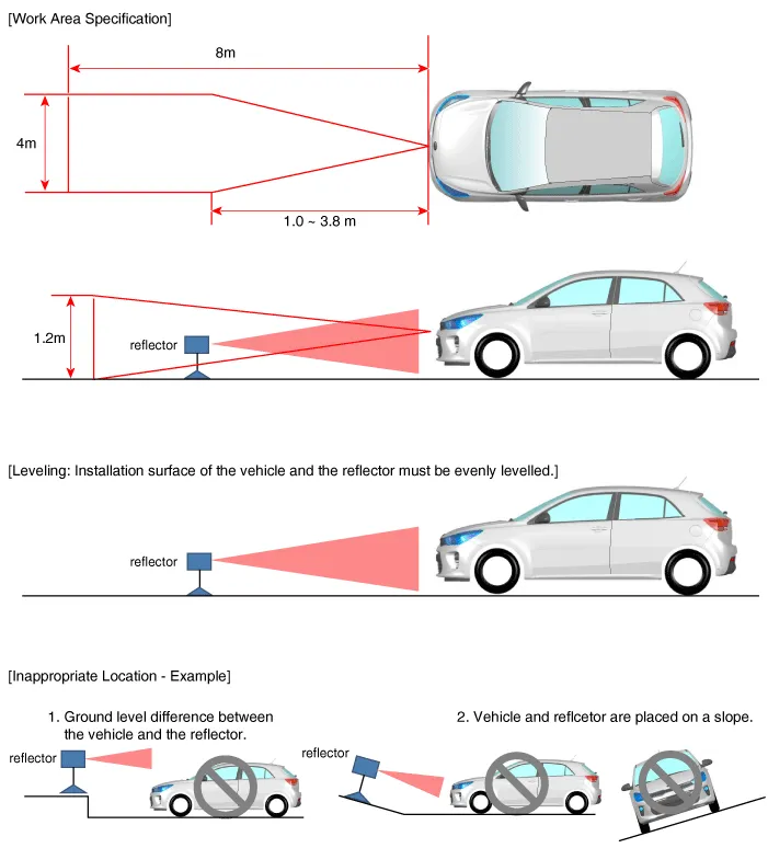
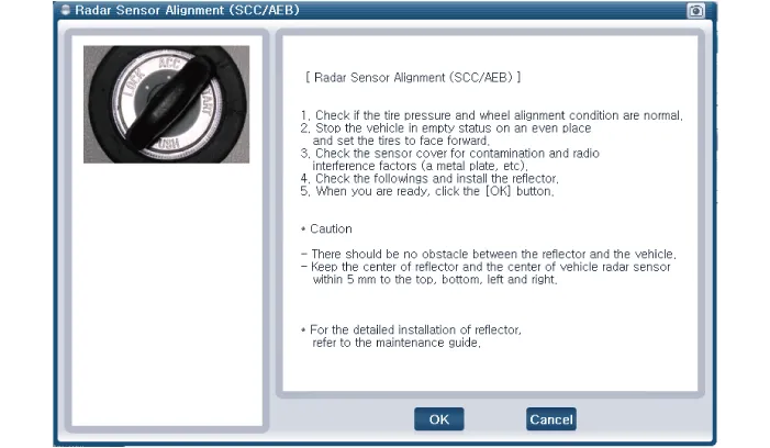
Park the vehicle on a level ground.
|
| 2. |
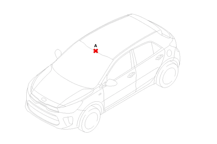
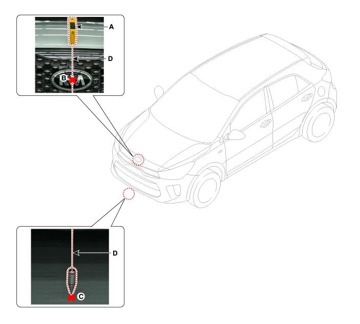
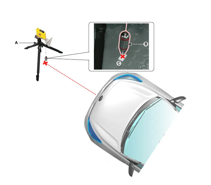
Mark the center point on top of wind glass (A).
|
| 3. |
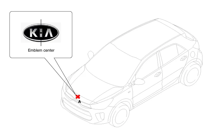
Mark the center point of emblem (A).
|
| 4. |
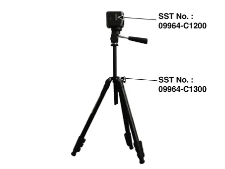
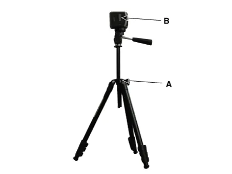
Mount the SCC Calibration Laser [SST No. : 09964-C1200] onto the tripod [SST No. : 09964-C1300].
|
| 5. |
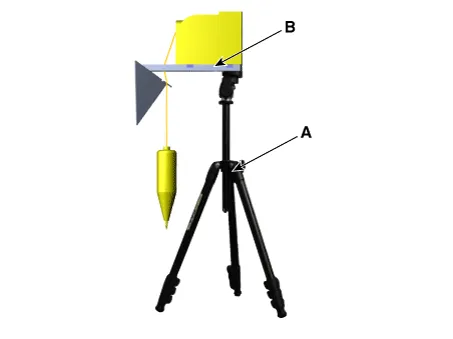
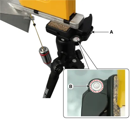
By using the SCC Calibration Reflector [SST No. : 09964-C1100] (A), adjust the wire (D) so that the center point of emblem (B) and the center point on the ground (C) are perpendicular to each other.
|
| 6. |
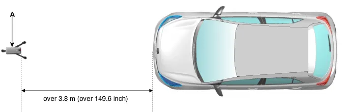
Install the vertical/horizontal laser [SST No. : 09964-C1200] (A) at least 3.8 m to the front of the vehicle.
|
| 7. |
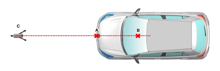
Match the vertical line of laser to (A) and (B) using the vertical/horizontal laser (C) [SST No. : 09964-C1200].
|
| 8. |
Mark (C) at 1.0 - 3.8 m (39.3 - 149.6 inch) from (A) in front of the vehicle.
|

| 9. |
Remove the SCC Calibration Laser [SST No. : 09964-C1200] (B) from the tripod [SST No. : 09964-C1300] (A).
|
| 10. |
Mount the reflector [SST No. : 09964-C1100] (B) onto the tripod [SST No. : 09964-C1300] (A).
|
| 11. |
Align the vertical weight (B) of the SCC Calibration Reflector [SST No. : 09964-C1100] (A) with the point (C).
|
| 12. |
Using the bubble level (B) of the tripod [SST No. : 09964-C1300] (A), set the reflector horizontally.
|
| 13. |
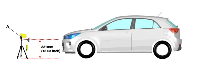
Set the height of the SCC calibration reflector [SST No. : 09964-C1100] (A) to 331mm (13.03inch).
|
| 14. |
Visually check again the radar sensor and the surface of the front bumper for the following.
|
| 15. |
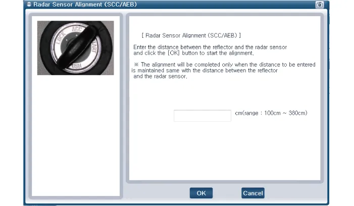
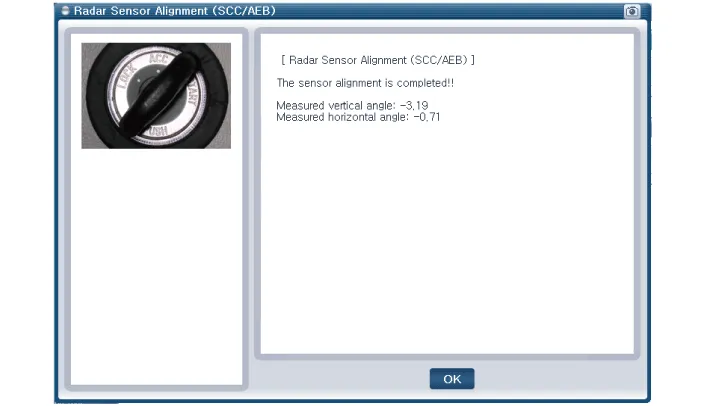
Connect the KDS/GDS to the DLC of the vehicle and start sensor alignment.
|
| 16. |
After correctly selecting the vehicle model, select "AEB Alignment" from the auxiliary functions in KDS/GDS Menu.
|
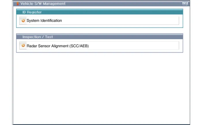
| 17. |
Perform sensor alignment as indicated on the KDS/GDS monitor.
|
| 18. |
In case of sensor alignment failure, check the alignment conditions. Turn the ignition key OFF, then reperform the sensor alignment procedure. |
Description and operation Description Introduction of quick brake warning system (ESS) In case of quick brake by driver, the brake lamp or turn signal is blinked to warn against the vehicle at rear.
Specifications Specifications Items Specification Hood Type Rear hinged, gas lifter type Front Door Construction Front hinged, frame door construction Regulator system Wire drum type Locking system Pin-fork system Rear Door Construction Front hinged, frame door construction Regulator system Wire drum type Locking system Pin-fork system Tail Gate Type Front hinged, gas lifter type Seat Belts Front 3 point type with Emergency Locking Retractor (E.
Other information:
Kia Rio 2017-2023 YB Service Manual: Power Door Lock Switch
Repair procedures Removal • When removing with a flat-tip screwdriver or remover, wrap protective tape around the tools to prevent damage to components.
Kia Rio 2017-2023 YB Service Manual: Heater Unit
Components and components location Component Location Components 1. Heater pipe cover 2. Heater core 3. Mode control actuator 4. Mode control actuator bracket 5. Mode control main lever 6.
Categories
- Manuals Home
- Kia Rio Owners Manual
- Kia Rio Service Manual
- Heating,Ventilation, Air Conditioning
- Cooling System
- Body (Interior and Exterior)
- New on site
- Most important about car
