Kia Rio: Automatic Transaxle Control System / Transaxle Control Module (TCM)
Description and operation
| Description |
The module receives and processes signals from various sensors and implements a wide range of transaxle controls to ensure optimal driving conditions for the driver.
Functions
| • |
Monitors the vehicle's operating conditions to determine the optimal gear setting. |
| • |
Performs a gear change if the current gear setting differs from the identified optimal gear setting. |
| • |
Determines the need for torque converter clutch activation and engages the clutch accordingly. |
| • |
Calculates the optimal line pressure level by constantly monitoring the torque level and adjusts the pressure accordingly. |
| • |
Diagnoses the faults and failures for automatic transaxle. |
Schematic diagrams
| TCM Terminal Function |
Connector [A]
|
Pin |
Description |
|
3 |
PCSV-D |
|
4 |
PCSV-A |
|
5 |
LINE_VFS |
|
24 |
PCSV-B |
|
43 |
PCSV-C |
|
45 |
SCSV-A |
|
54 |
Manual mode "select" switch |
|
57 |
Inhibitor switch "D" input |
|
58 |
Inhibitor switch "R" input |
|
62 |
Manual mode "up" switch |
|
64 |
Power |
|
68 |
Ground |
|
79 |
Oil temperature sensor (-) |
|
80 |
Oil temperature sensor (+) |
|
84 |
Inhibitor switch "P" input |
|
85 |
Power |
|
87 |
Ground |
|
88 |
Ground |
|
99 |
Output speed sensor (+) signal |
|
100 |
Input speed sensor (+) signal |
|
104 |
Inhibitor switch "N" input |
|
105 |
Manual mode "down" switch |
Connector [K]
|
Pin |
Description |
|
5 |
Engine control relay "ON" input |
|
43 |
Output speed sensor ground |
|
82 |
Input speed sensor ground |
| Circuit Diagram |

Repair procedures
| Inspection |
| 1. |
TCM ground circuit test : Measure the resistance between TCM and chassis ground. (Inspect the terminal connected to the chassis ground with the back of harness connector as the inspection point of TCM side.)
|
| 2. |
TCM connector test : Disconnect the TCM connector and visually check the ground terminals on TCM side and harness side for bent pins or poor contact pressure. |
| 3. |
If problem is not found in Steps 1 and 2, the TCM could be faulty. If so, replace the TCM with a new one, and then check the vehicle again. If the vehicle operates normally then the problem was likely with the TCM. |
| 4. |
Reinspection of original TCM : Install the original TCM (probably broken) into a known-good vehicle and check the vehicle. If the problem occurs again, replace the original TCM with a new one. If the problem does not reoccur, this is an intermittentproblem and other part may be faulty. |
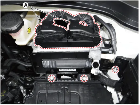
| Removal |
| 1. |
Remove the battery. (Refer to Engine Electrical System - "Battery") |
| 2. |
Disconnect the TCM connectors (A) and then remove the TCM after loosening the bolts and nut.
|
| Installation |
| 1. |
Install in the reverse order of removal. |
|

Description and operation Description Automatic transaxle control system relies on various measurements to determine the current control status and determine the necessary compensation values.
Specifications Specification Item Specification Type *NTC thermistor Temp.
Other information:
Kia Rio 2017-2023 YB Service Manual: Smart Key System
Specifications Specifications Smart Key Unit Items Specification Rated voltage DC 12 V Operating voltage DC 9 - 16 V Operating temperature -31 - 167°F (-35 - 75°C) Load Max.
Kia Rio 2017-2023 YB Service Manual: Heating,Ventilation, Air Conditioning
Specifications Specification Air Conditioner Item Specification Compressor Type DVE12 Oil type & Capacity PAG 30, 120 ± 10 g Displacement 122 cc/rev Expansion valve Type
Categories
- Manuals Home
- Kia Rio Owners Manual
- Kia Rio Service Manual
- Motor Driven Power Steering
- Maintenance
- Steering System
- New on site
- Most important about car
