Kia Rio: Smart Key System / Smart Key Unit
Components and components location
| Components |

Connector Pin Information
|
No. |
Connector A |
Connector B |
Connector C |
|
1 |
- |
IGN2 Relay_output |
Battery (+)_Signal |
|
2 |
SSB Switch1 signal_input |
P-CAN (Low) |
- |
|
3 |
Driver door outside handle switch_input |
P-CAN (High) |
Immobilizer antenna (Power)_output |
|
4 |
- |
C-CAN (High) |
Driver outside handle antenna (Power)_output |
|
5 |
- |
C-CAN (Low) |
Passenger outside handle antenna (Power)_output |
|
6 |
- |
SSB Amber illumination_output |
Bumper antenna (Power)_output |
|
7 |
RPM Signal_input |
- |
Interior antenna 1 (Power)_output |
|
8 |
Start signal feedback_input |
SSB Illumination (+)_output |
Interior antenna 2 (Power)_output |
|
9 |
IGN2 |
ESCL Enable_output |
Interior antenna 3 (Power)_output |
|
10 |
- |
Battery (+)_Power |
- |
|
11 |
Starter relay_output |
IGN1 Relay_output |
- |
|
12 |
Ground_Power1 |
ESCL (COM) |
- |
|
13 |
SSB Switch2 signal_input |
EMS (COM) |
ESCL_Ground (-)_output |
|
14 |
Assist door outside handle switch_input |
- |
Immobilizer antenna (Ground)_output |
|
15 |
- |
SSB Illumination (-)_output |
Driver outside handle antenna (Ground)_output |
|
16 |
AT : "P" Positon_input MT : Clutch switch_input |
SSB Illumination (Blue)_output SSB Illumination (Red)_output |
Passenger outside handle antenna (Ground)_output |
|
17 |
ESCL Unlock switch_input |
- |
Bumper antenna (Ground)_output |
|
18 |
Wheel speed sensor_input |
Exterior buzzer_output |
Interior antenna 1 (Ground)_output |
|
19 |
ACC Signal_input |
- |
Interior antenna 2 (Ground)_output |
|
20 |
IGN1 |
ESCL (+)_output |
Interior antenna 3 (Ground)_output |
|
21 |
Brake switch_input |
|
- |
|
22 |
ACC Relay_output |
Ground_Power2 |
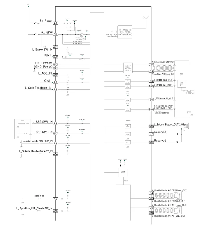
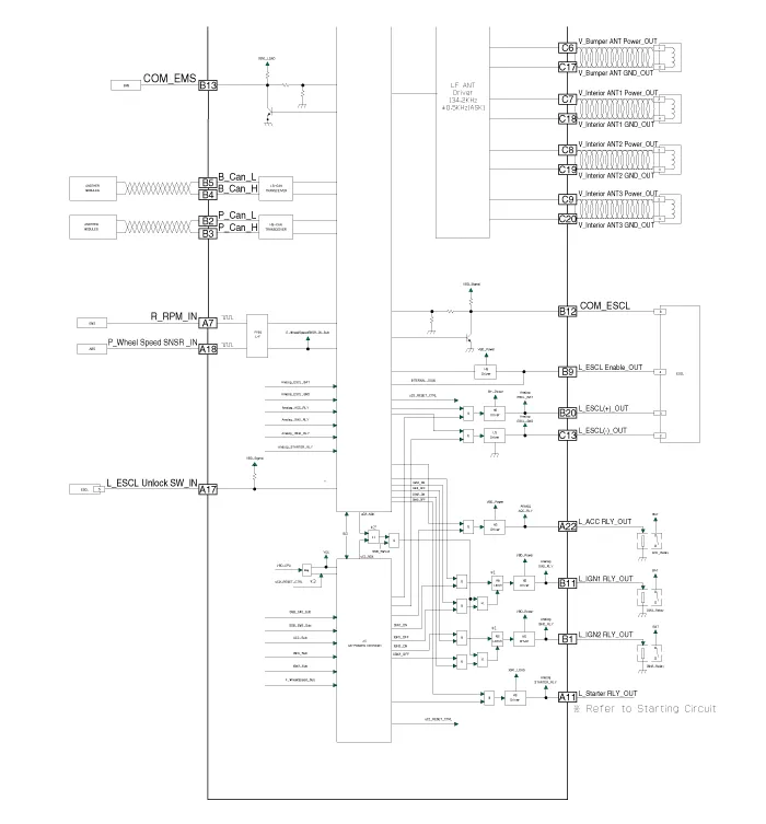
Schematic diagrams
| Circuit Diagram |
Repair procedures
| Removal |
Put on gloves to prevent hand injuries. |

|

Smart Key Unit
| 1. |
Disconnect the negative (-) battery terminal. |
| 2. |
Remove the glove box. (Refer to Body - "Glove Box") |
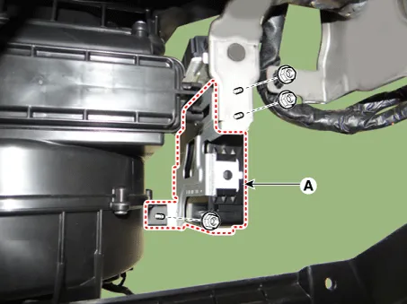
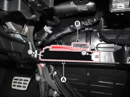
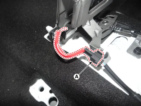
| 3. |
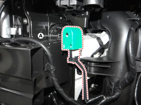
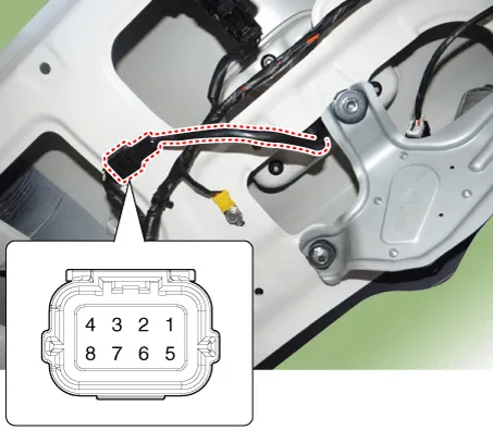
Remove the smart key unit (B) after disconnecting the connectors (A).
|

| 4. |
Remove the smart key unit (A) after loosening the mounting nuts.
|
Interior 1 Antenna
| 1. |
Disconnect the negative (-) battery terminal. |
| 2. |
Remove the heater and A/C controll unit. (Refer to Heating,Ventilation, Air Conditioning - "Heater & A/C Control Unit (Manual)") (Refer to Heating, Ventilation, Air conditioning - "Heater & A/C Control Unit (FATC)") |
| 3. |
Remove the interior 1 antenna (A) after loosening the mounting screws and disconnecting the connector (B).
|
Interior 2 Antenna
| 1. |
Disconnect the negative (-) battery terminal. |
| 2. |
Remove the floor console assembly. (Reger to Body - "Floor Console Assembly") |
| 3. |
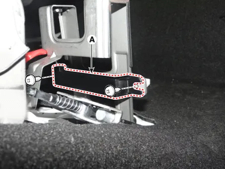
Disconnect the interior 2 antenna connector (A).
|
| 4. |
Remove the interior 2 antenna (A) after loosening the mounting screws.
|
Tailgate Antenna
| 1. |
Disconnect the negative (-) battery terminal. |
| 2. |
Remove the rear transverse trim. (Reger to Body - " Rear Transverse Trim") |
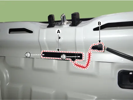
| 3. |
Remove the tailgate antenna (A) after loosening the mounting nuts and disconnecting the connector (B).
|
Rear Bumper Antenna
| 1. |
Disconnect the negative (-) battery terminal. |
| 2. |
Remove the rear bumper assembly. (Refer to Body - "Rear Bumper Assembly") |
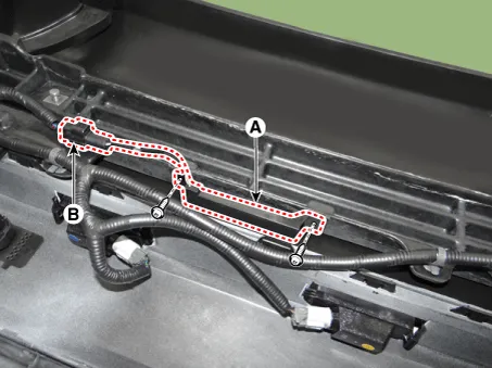
| 3. |
Remove the rear bumper antenna (A) after loosening the mounting screws and disconnecting the connector (B).
|
Buzzer
| 1. |
Disconnect the negative (-) battery terminal. |
| 2. |
Remove the front bumper assembly. (Refer to Body - "Front Bumper Assembly") |
| 3. |
Remove the buzzer (A) after disconnecting the connector.
|
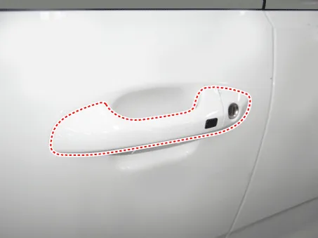
Door Outside Handle
| 1. |
Disconnect the negative (-) battery terminal. |
| 2. |
Remove the front door outside handle. (Refer to Body - "Front Door Outside Handle")
|

Tailgate Open Switch
| 1. |
Disconnect the negative (-) battery terminal. |
| 2. |
Remove the back view camera assembly. (Refer to Body Electrical System - "Back View Camera System") |
| 3. |
Remove the tailgate open switch assembly (A) after loosening the mounting screws.
|

| Inspection |
Smart Key Unit
(Refer to Smart Key System - "Smart Key Diagnostic")
Smart Key Switch
(Refer to Smart Key System - "Smart Key Diagnostic")
Antenna
(Refer to Smart Key System - "Smart Key Diagnostic")
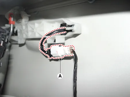
Door Outside Handle
| 1. |
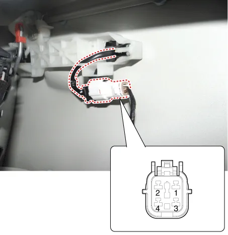
Disconnect the front door outside handle connector (A).
|
| 2. |
Check for continuity between terminals No 2 and No 4.
|
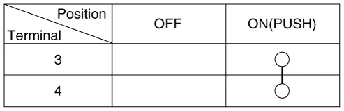
Tailgate Open Switch
| 1. |
Check for continuity between the tailgate open switch terminals.
|
| 2. |
If continuity is not specified, inspect the switch
|
| Installation |
Smart Key Unit
| 1. |
Install the smart key unit after connecting the connectors. |
| 2. |
Install the glove box. |
| 3. |
Connect the negative (-) battery terminal and check the smart key system. |
Interior 1 Antenna
| 1. |
Install the interior 1 antenna. |
| 2. |
Install the heater and A/C controll unit. |
| 3. |
Install the negative (-) battery terminal and check the smart key system. |
Interior 2 Antenna
| 1. |
Install the interior 2 antenna. |
| 2. |
Install the floor console assembly. |
| 3. |
Connect the negative (-) battery terminal and check the smart key system. |
Tailgate Antenna
| 1. |
Install the tailgate antenna. |
| 2. |
Install the rear transverse trim. |
| 3. |
Connect the negative (-) battery terminal and check the smart key system. |
Rear Bumper Antenna
| 1. |
Install the rear bumper antenna. |
| 2. |
Install the rear bumper assembly. |
| 3. |
Connect the negative (-) battery terminal and check the smart key system. |
Buzzer
| 1. |
Install the buzzer. |
| 2. |
Install the front bumper assembly. |
| 3. |
Connect the negative (-) battery terminal and check the smart key system. |
Door Outside Handle
| 1. |
Install the front door outside handle. |
| 2. |
Connect the negative (-) battery terminal and check the smart key system. |
Tailgate Open Switch
| 1. |
Install the tailgate open switch assembly. |
| 2. |
Install the back view camera assembly. |
| 3. |
Install the tailgate outside handle assembly. |
| 4. |
Connect the tailgate outside handle assembly connector. |
| 5. |
Install the tailgate trim. |
| 6. |
Install the negative (-) battery terminal and check the smart key system. |
Repair procedures Smart Key Smart Key Code Saving 1. Connect the DLC cable of KDS/GDS to the data link connector (16 pins) in driver side crash pad lower panel, turn the power on KDS/GDS.
Repair procedures Inspection Self Diagnosis With Scan Tool It will be able to diagnose defects of SMART KEY system with KDS/GDS quickly.
Other information:
Kia Rio 2017-2023 YB Service Manual: Power Door Lock Module
Components and components location Components 1. Door lock/unlock knob cable 2. Door latch assembly Repair procedures Inspection • When removing with a flat-tip screwdriver or remover, wrap
Kia Rio 2017-2023 YB Service Manual: Smart Key Diagnostic
Repair procedures Inspection Self Diagnosis With Scan Tool It will be able to diagnose defects of SMART KEY system with KDS/GDS quickly. KDS/GDS can operates actuator forcefully, input/output value monitoring and self diagnosis. The following three features will be major problem in SMART KEY system.
Categories
- Manuals Home
- Kia Rio Owners Manual
- Kia Rio Service Manual
- Body (Interior and Exterior)
- Engine Control / Fuel System
- Heating,Ventilation, Air Conditioning
- New on site
- Most important about car
