Kia Rio: Seat Electrical / Seat Heater
Components and components location
| Component Location |

| 1. Seat heater unit (Passenger
seat only) 2. Front seat back heater |
3. Front seat cushion heater
|
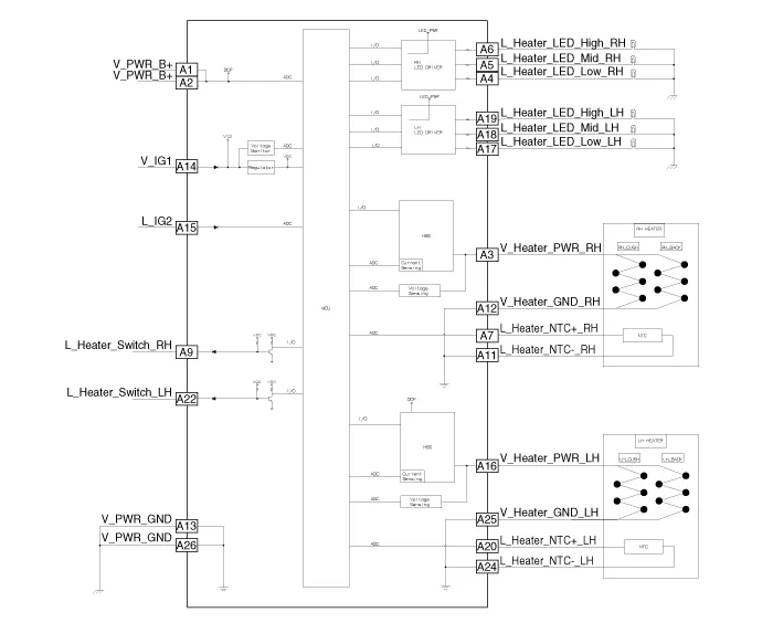
Schematic diagrams
| Circuit Diagram |
Repair procedures
| Inspection |
| 1. |
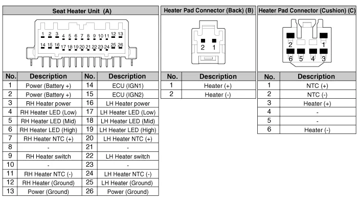
Check for continuity and measure the resistance between terminals No 3 and No 6.
|

| 2. |
Operate the seat heater after connecting the connector, and then check the thermostat by measuring the temperature of seat surface.
|
| Removal |
| 1. |
Disconnect the negative (-) battery terminal. |
| 2. |
Remove the front seat assembly. (Refer to Body - "Front Seat Assembly") |
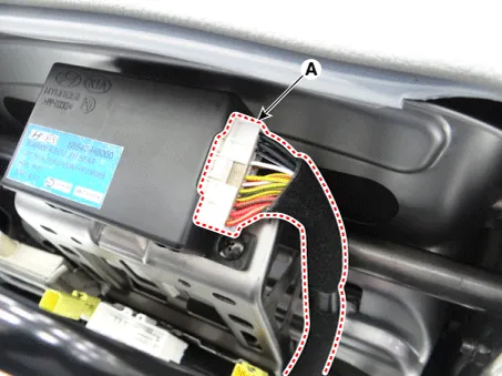
| 3. |
Disconnect the seat heater unit connector (A).
|
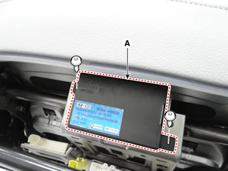
| 4. |
Remove the seat heater unit (A) after loosening the mounting screws.
|
| Installation |
| 1. |
Install the seat heater unit and connecting the connector. |
| 2. |
Install the front seat assembly. |
| 3. |
Connect the negative (-) battery terminal. |
Components and components location Components 1. Driver side seat heater switch 2. Passenger side seat heater switch Description and operation Description Seat Heater Smart Control Technology • To prevent low temperature burn, seat heater temperature will automatically be lowered after a certain period of time.
Other information:
Kia Rio 2017-2023 YB Service Manual: Ambient Temperature Sensor
Description and operation Description The ambient temperature sensor is located at the front of the condenser and detects ambient air temperature. It is a negative type thermistor; resistance will increase with lower temperature, and decrease with higher temperature.
Kia Rio 2017-2023 YB Service Manual: Intake Actuator
Description and operation Description The intake actuator is located at the blower unit. It regulates the intake door by signal from control unit. Pressing the intake selection switch will shift between recirculation and fresh air modes.
Categories
- Manuals Home
- Kia Rio Owners Manual
- Kia Rio Service Manual
- Maintenance
- Brake System
- Heating,Ventilation, Air Conditioning
- New on site
- Most important about car
