Kia Rio: ESC (Electronic Stability Control) System / Rear Wheel Speed Sensor
Components and components location
| Components |
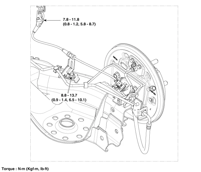
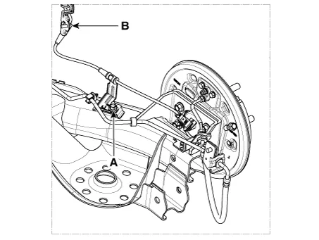
Drum type
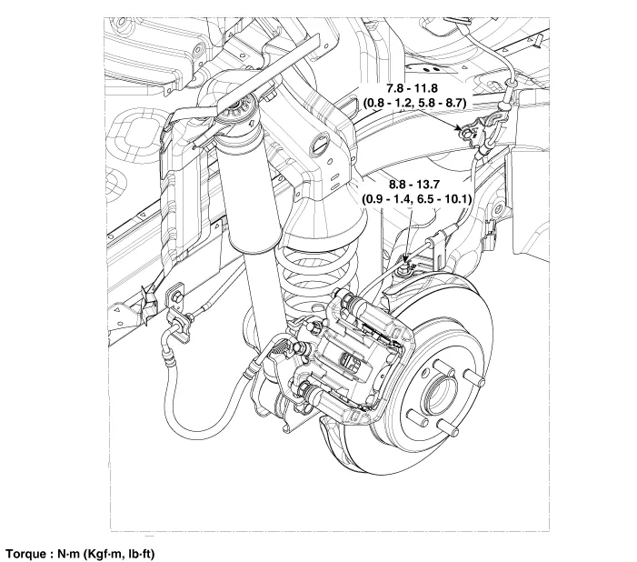
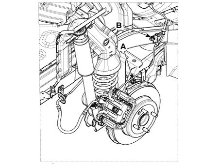
Disc type
Repair procedures
| Removal |
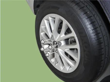
| 1. |
Remove the rear wheel & tire.
|
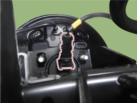
| 2. |
Disconnect the rear wheel speed sensor.
|
| 3. |
Loosen the nut (A) and bolt (B).
Drum type
Disc type
|
| 4. |
Remove the rear seat. (Refer to body -"Rear Seat Assembly") |
| 5. |
Remove the door scuff trim. (Refer to body -"Door Scuff Trim") |
| 6. |
Disconnect the rear wheel speed sensor connector. |
| Inspection |
| 1. |
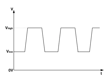
Measure the output voltage between the terminal of the wheel speed sensor and the body ground.
|


| 2. |
Compare the change of the output voltage of the wheel speed sensor to the normal change of the output voltage as shown below.
|
| Replacement |
Rear Wheel Speed Sensor Cap
| 1. |
Remove the rear wheel hub bearing assembly. (Refer to Driveshaft and axle - "Rear Axle Assembly") |
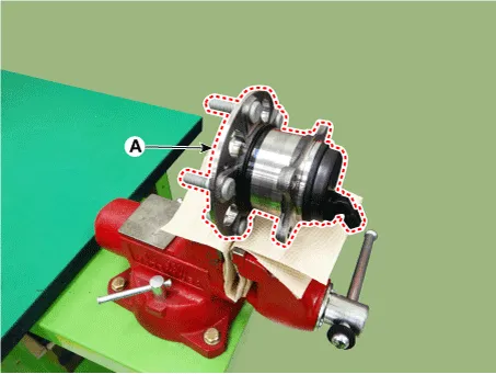
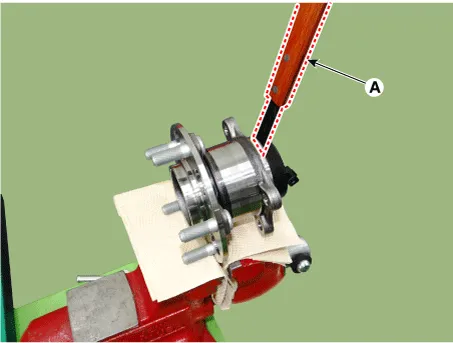
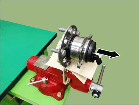
| 2. |
Fix the rear hub bearing assembly (A) on the vise.
|
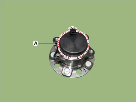
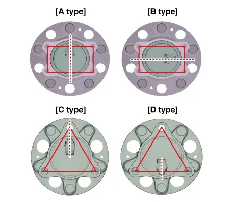
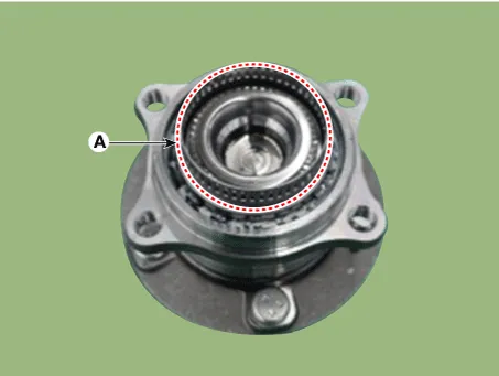
| 3. |
Check the direction of the sensor cap (A).
|
| 4. |
Remove the sensor cap by hammering on a gap between sensor cap and hub bearing assembly using a scraper (A).
|
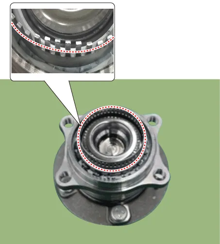
| 5. |
Check if distorted or damaged the tone wheel or encoder (A).
|
| 6. |
Position the sensor cap to the same direction of sensor cap connector (A) as you checked before removing.
|
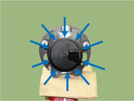
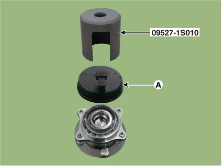
| 7. |
Install the sensor cap (A) with the special service tool (09527-1S010).
|
| 8. |
Install the rear wheel hub bearing assembly. (Refer to Driveshaft and axle - "Rear Axle Assembly") |
Components and components location Components 1. Front wheel speed sensor connector 2. Front wheel speed sensor Repair procedures Removal 1.
Description and operation Description 1. The ESC OFF switch is for the user to turn off the ESC system. 2.
Other information:
Kia Rio 2017-2023 YB Service Manual: High Mounted Stop Lamp
Repair procedures Removal 1. Disconnect the negative (-) battery terminal. 2. Open the tailgate. 3. Remove the high mounted stop lamp (A) after loosening the mounting nuts.
Kia Rio 2017-2023 YB Service Manual: Rear Washer Motor
Repair procedures Inspection 1. With the washer motor connected to the reservoir tank, fill the reservoir tank with water. Before filling the reservoir tank with water, check the filter for foreign material or conta
Categories
- Manuals Home
- Kia Rio Owners Manual
- Kia Rio Service Manual
- Timing Chain
- Emission Control System
- General Information
- New on site
- Most important about car
