Kia Rio: Brake System / Rear Drum Brake
Components and components location
| Components |
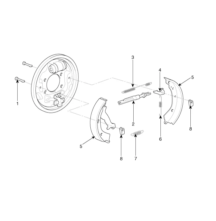
| 1. Shoe hold down pin 2. Shoe adjuster 3. Upper return spring 4. Adjusting lever |
5. Shoe 6. Adjusting spring 7. Lower return spring 8. Shoe hold spring |
Repair procedures
| Removal |
|

| 1. |
Release the parking brake. |
| 2. |
Remove the rear wheel & tire.
|

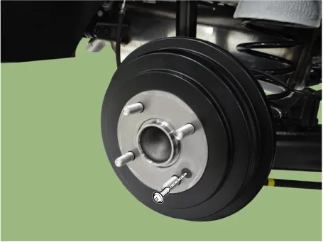
| 3. |
Remove the rear brake drum screw.
|
| 4. |
Remove the upper return spring.
|
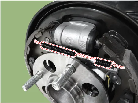
| 5. |
Remove the lower return spring.
|

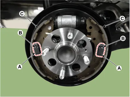
| 6. |
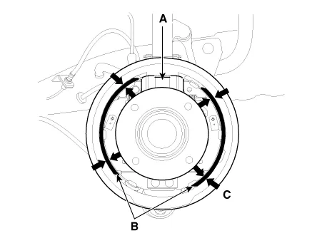
Remove the shoe hold springs (A) and shoe hold pins (B) and then remove brake shoe (C). Make sure not to damage the dust cover on the wheel cylinder.
|
| 7. |
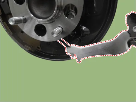
Disconnect the parking brake cable from lining.
|
| 8. |
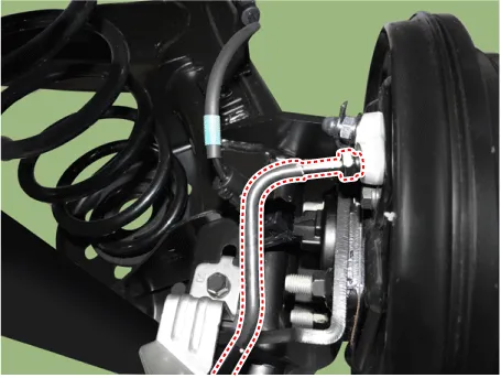
Remove the brake tube flare nut.
|
| 9. |
Loosen the wheel cylinder bolts and then remove the wheel cylinder.
|

| Installation |
|
| 1. |
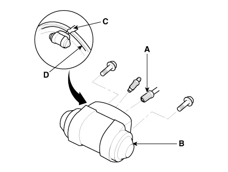
Apply sealant (C) between the wheel cylinder (B) and backing plate (D), and install the wheel cylinder.
|
| 2. |
Install the brake tube flare nut.
|
| 3. |
Connect the parking brake cable from lining.
|
| 4. |
Remove the shoe hold springs (A) and shoe hold pins (B) and then remove brake shoe (C). Make sure not to damage the dust cover on the wheel cylinder.
|
| 5. |
Install the shoe hole down pins (B) and the shoe hole down springs (A). |
| 6. |
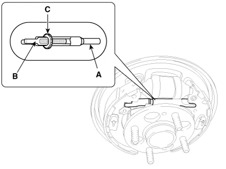
Clean the threaded portions of adjuster sleeve (A) and push rod female (B). Coat the threads of the adjuster assembly with grease. To shorten the clevises, turn the adjuster bolt (C).
|
| 7. |
Hook the shoe adjuster lever (C), then install it to the brake shoe.
|

| 8. |
Install the adjuster assembly (B) and upper return spring (A) as right direction. Be careful not to damage the wheel cylinder dust covers.
|
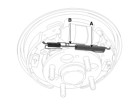
| 9. |
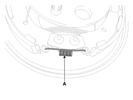
Install the lower return spring (B).
|
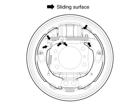
| 10. |
Apply brake cylinder grease or equivalent rubber grease to the sliding surfaces shown. Don't get grease on the brake linings.
|
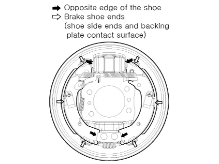
| 11. |
Apply brake cylinder grease or equivalent rubber grease to the brake shoe ends and opposite edges of the shoes shown. Don't get grease on the brake linings.
|
| 12. |
Install the rear brake drum.
|
| 13. |
If the wheel cylinder has been removed, bleed the brake system. |
| 14. |
Depress the brake pedal several times to set the self-adjusting brake. |
| 15. |
Adjust the parking brake. |
| Inspection |
|

|
| 1. |
Raise the rear of the vehicle, and make sure it is securely supported. |
| 2. |
Release the parking brake, and remove the rear brake drum. |
| 3. |
Check the wheel cylinder (A) for leakage.
|
| 4. |
Check the brake linings (B) for cracking, glazing, wear, and contamination. |
| 5. |
Measure the brake lining thickness (C).Measurement does not include brake shoe thickness.
|
| 6. |
If the brake lining thickness is less than the service limit, replace the brake shoes as a set. |
| 7. |
Check the bearings in the hub unit for smooth operation. If it requires servicing, replace it. |
| 8. |
Measure the inside diameter of the brake drum with inside vernier calipers.
|
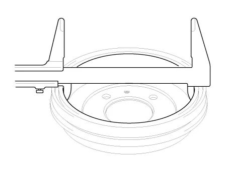
| 9. |
If the inside diameter of the brake drum is more than the service limit, replace the brake drum. |
| 10. |
Check the brake drum for scoring, grooves, and cracks. |
| 11. |
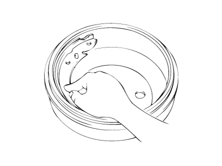
Inspect the brake lining and drum for proper contact.
|
| 12. |
Inspect the wheel cylinder outside for excessive wear and damage. |
| 13. |
Inspect the backing plate for wear or damage. |
Components and components location Components 1. Cable cuide & Lever 2. Caliper body 3. Torque member 4.
Components and components location Components 1. Brake pedal member assembly 2. Stop lamp switch 3. Brake pedal arm Schematic diagrams Schematic Diagram System circuit diagram Terminal function Terminal Description 1 IGN1 2 Engine Control Module (ECM) 3 B+ 4 Stop Lamp Troubleshooting Troubleshooting 1.
Other information:
Kia Rio 2017-2023 YB Service Manual: Power Window Switch
Components and components location Components Driver Power Window Switch Connector Pin Information [Front / Rear Driver Safety - Auto Up/Down] [LHD] No. Description No. Description 1 Front right power window (Up) 10
Kia Rio 2017-2023 YB Service Manual: Temperature Control Actuator
Description and operation Description The heater unit includes mode control actuator and temperature control actuator. The temperature control actuator is located at the heater unit. It regulates the temperature by the procedure as follows.
Categories
- Manuals Home
- Kia Rio Owners Manual
- Kia Rio Service Manual
- Engine Mechanical System
- Battery
- Maintenance
- New on site
- Most important about car
