Kia Rio: Power Door Mirrors / Power Door Mirror Actuator
Components and components location
| Components |
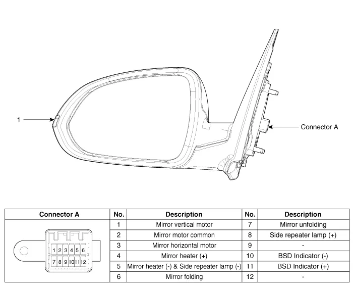
| 1. Side repeater lamp |
Repair procedures
| Inspection |
| 1. |
Disconnect the negative (-) battery terminal. |
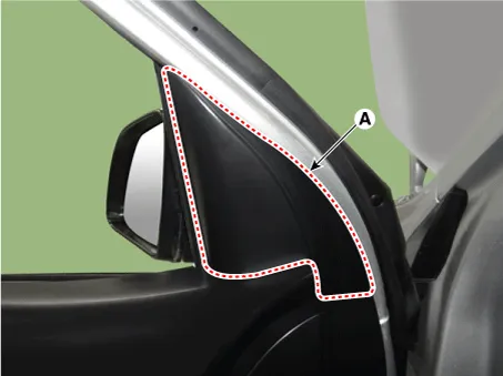
| 2. |
Remove the front door quadrant inner cover (A).
|
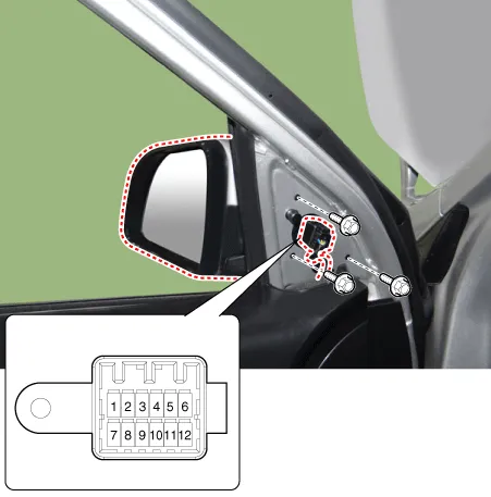
| 3. |
Disconnect the power door mirror connector from the harness.
|
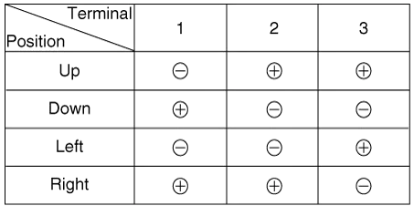
| 4. |
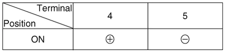
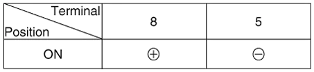
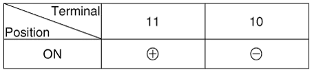
Apply battery voltage to each terminal as shown in the table and verify that the mirror operates properly. [Mirror Control (LH/RT)]
[Mirror Heater]
[Side Repeater Lamp]
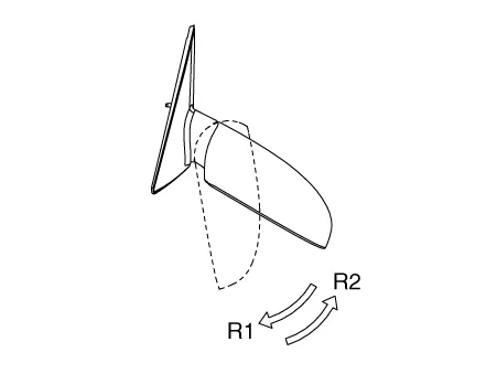
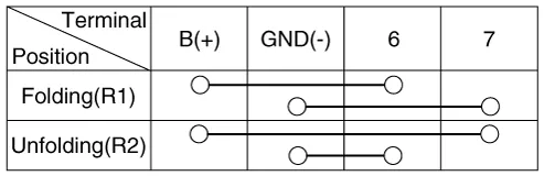
[Folding Mirror]
[BSD Indicator]
|
| Removal |
| 1. |
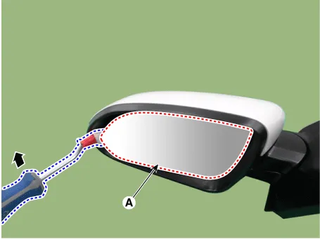
After inserting the flat-bladed screwdriver or remover as shown in the illustration below, remove the mirror (A) by applying a momentary force.
|

| 2. |
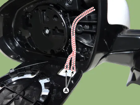
Disconnect the heater connectors (A).
|
| 3. |
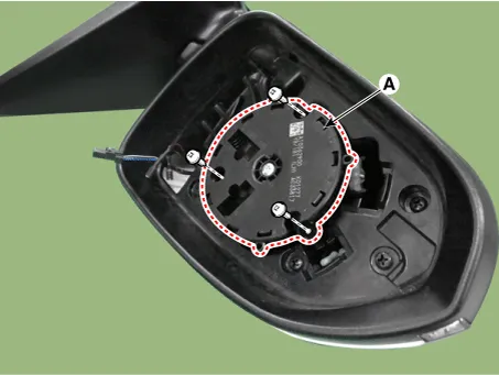
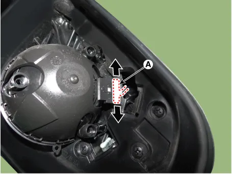
Remove the mirror actuator (A) after loosening the screws.
|
| 4. |
Disconnect the mirror actuator connector (A).
|
| Installation |
| 1. |
Install in the reverse order of removal. |
Components and components location Component Driver Power Window Switch Schematic diagrams Circuit Diagram [Non-Folding Mirror Type] [Folding Mirror Type] Repair procedures Removal 1.
Components and components location Component Location 1. Driver power window switch 2. Assist power window switch 3.
Other information:
Kia Rio 2017-2023 YB Service Manual: Rear Wiper Motor
Repair procedures Inspection Rear Wiper Motor 1. Remove the connector from the rear wiper motor. 2. Connect positive (+) battery cables to terminal 4 and negative (-) battery cables to terminal 3 respectively.
Kia Rio 2017-2023 YB Service Manual: Rear Washer Motor
Repair procedures Inspection 1. With the washer motor connected to the reservoir tank, fill the reservoir tank with water. Before filling the reservoir tank with water, check the filter for foreign material or conta
Categories
- Manuals Home
- Kia Rio Owners Manual
- Kia Rio Service Manual
- CVVT & Camshaft
- Engine Electrical System
- Maintenance
- New on site
- Most important about car
