
Kia Rio: Rear Suspension System / Rear Shock Absorber
Components and components location
| Components |
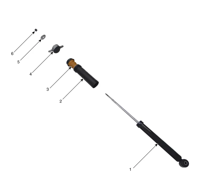
| 1. Shock absorber assembly
2. Dust cover 3. Bumper stopper |
4. Insulator 5. Retainer 6. Lock nut |
Repair procedures
| Removal |
| 1. |
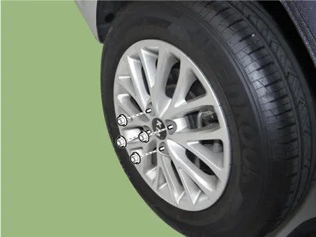
Remove wheel nuts, rear wheel and tire from rear hub.
|

| 2. |
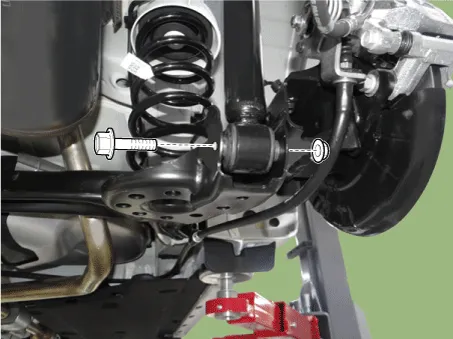
Loosen the shock absorber lower bolt.
|
| 3. |
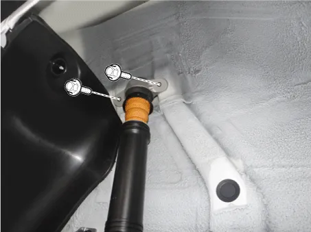
Loosen the bolts and then remove the rear shock apsorber.
|
| 4. |
Install in the reverse order of removal. |
| Inspection |
| 1. |
Check the rubber parts for wear and deterioration. |
| 2. |
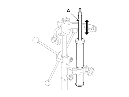
Compress and extend the piston rod (A) and check that there is no abnormal resistance or unusual sound during operation.
|
Disposal
| 1. |
Fully extend the piston rod. |
| 2. |
Drill a hole on the (A) section to remove gas from the cylinder.
|

Components and components location Components [Drum Type] 1. Torsion beam axle 2. Rear spring 3. Rear drum brake disc [Disc Type] 1.
Repair procedures Removal 1. Remove wheel nuts, rear wheel and tire from rear hub. Tightening torque: 107.
Other information:
Kia Rio 2017-2023 YB Service Manual: Immobilizer System
Schematic diagrams Circuit Diaram Description and operation Description The immobilizer system will disable the vehicle unless the proper ignition key is used, in addition to the currently available anti-theft systems such as car alarms, the immobilizer system aims to drastically reduce the rate of auto theft.
Kia Rio 2017-2023 YB Service Manual: Intake Actuator
Description and operation Description The intake actuator is located at the blower unit. It regulates the intake door by signal from control unit. Pressing the intake selection switch will shift between recirculation and fresh air modes.
Categories
- Manuals Home
- Kia Rio Owners Manual
- Kia Rio Service Manual
- Heating,Ventilation, Air Conditioning
- Fuse/relay panel description
- Restraint
- New on site
- Most important about car
