Kia Rio: Lubrication System / Oil Pan
Components and components location
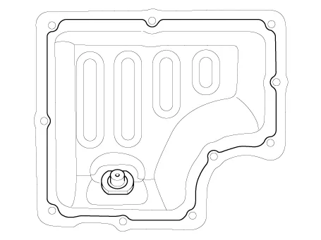
| Components |
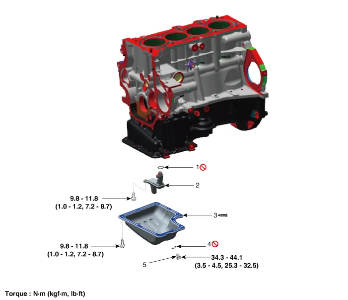
| 1. Oil screen O-ring 2. Oil screen 3. Oil pan |
4. Drain plug gasket 5. Drain plug |
Repair procedures
| Removal |
| 1. |
Remove the engine room under cover. (Refer to Engine And Transaxle Assembly - "Engine Room Under Cover") |
| 2. |
Drain engine oil. (Refer to Lubrication System - "Engine Oil") |
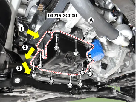
| 3. |
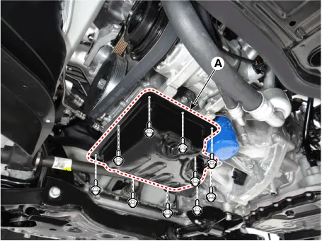
Remove the oil pan (A). Insert the blade of SST (09215-3C000) between the ladder frame and the oil pan. Cut off applied sealer and remove the oil pan.
|

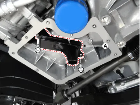
| 4. |
Remove the oil screen (A).
|
| Installation |
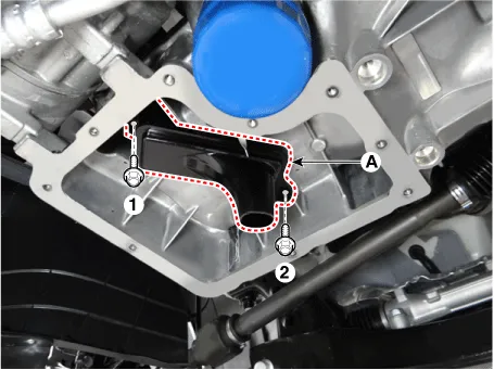
| 1. |
Install the oil screen (A), with a new O-ring. Tighten the bolts with the order blow.
|
| 2. |
Install the lower oil pan.
|
| 3. |
Install the lower oil pan (A).
Uniformly tighten the bolts in several passes.
|
| 4. |
Refill engine with engine oil. |
Repair procedures Removal and Installation 1. Disconnect the oil pressure switch connector (A) and then remove the oil pressure switch (B).
Repair procedures Removal and Installation 1. Remove the oil level gauge (A). 2. Remove the intake manifold.
Other information:
Kia Rio 2017-2023 YB Service Manual: License Lamps
Repair procedures Removal 1. Disconnect the negative (-) battery terminal. 2. Remove the license lamp assembly (A) after pressing the locking pin. 3. Disconnect the license lamp connector (A).
Kia Rio 2017-2023 YB Service Manual: Condenser
Repair procedures Inspection 1. Check the condenser fins for clogging and damage. If clogged, clean them with water, and blow them with compressed air. If bent, gently bend them using a screwdriver or pliers. 2.
Categories
- Manuals Home
- Kia Rio Owners Manual
- Kia Rio Service Manual
- Engine Control / Fuel System
- General Information
- Body Electrical System
- New on site
- Most important about car
