
Kia Rio: Manual Transaxle System / Neutral Switch
Specifications
| Specifications |
|
Item |
Specified |
|
Type |
ON / OFF |
|
Operating condition |
Neutral gear |
|
Operating voltage |
10 V - 15 V |
|
Operating temperature |
-30°C to 100°C (-30°F to 212°F) |
Components and components location
| Component Location |
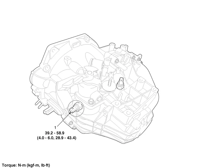
1. Neutral switch
Description and operation
| Description |
| • |
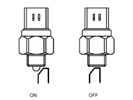
Neutral switch signal is transmitted to ECM in neutral state. |
| • |
The signal is blocked when gear is changed. |
| • |
When the signal is blocked, the ECM controls the fuel injection amount mapping value for 1st gear so that vehicle can start properly.
|
Repair procedures
| Inspection |
| 1. |
Remove the air cleaner assembly. (Refer to Engine Mechanical System - "Air Cleaner) |
| 2. |
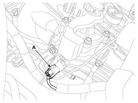
Disconnect the neutral switch connector (A).
|
| 3. |
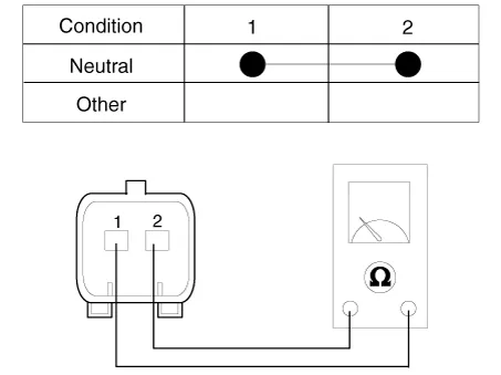
Check the continuity between power terminal and signal terminal.
|
| Removal |
| 1. |
Remove the air cleaner assembly. (Refer to Engine Mechanical System - "Air Cleaner) |
| 2. |
Disconnect the neutral switch connector (A).
|
| 3. |
Remove the neutral switch (A).
|
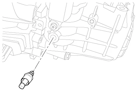
| Installation |
| 1. |
Install in the reverse order of removal. |
The neutral switch must be replaced with new one. (Do not reuse it.) |

Specifications Specifications Item Specified Type ON/OFF Operating condition Reverse gear Operating voltage 10V - 15V Operating temperatures -30°C to 100°C [-30°F to 212°F]" Components and components location Component Location 1.
Specifications Specifications Automatic Transaxle Item Specification Transaxle model A4CF1 Engine model Gasoline 1.
Other information:
Kia Rio 2017-2023 YB Service Manual: Auto Defogging Sensor (FATC only)
Description and operation Description The Auto Defogging Sensor is installed on front windshild glass. The Auto Defogging Sensor senses moisture on the windshild. The air conditioner control module receives the signal from the sensor and eliminate the fog by controlling the intake actuator, A/C, auto defogging actuator, blower m
Kia Rio 2017-2023 YB Service Manual: Heater Unit
Components and components location Component Location Components 1. Heater pipe cover 2. Heater core 3. Mode control actuator 4. Mode control actuator bracket 5. Mode control main lever 6.
Categories
- Manuals Home
- Kia Rio Owners Manual
- Kia Rio Service Manual
- Engine Oil and Filter
- Engine Mechanical System
- Maintenance
- New on site
- Most important about car
