Kia Rio: Manual Transaxle System / Manual Transaxle
Components and components location
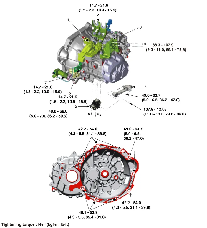
| Components |
|
1. Control shaft complete 2. Control cable bracket 3. Transaxle support bracket 4. Roll rod bracket |
5. Roll rod support bracket 6. Clutch tube bracket 7. Clutch release cylinder assembly |
Repair procedures
| Removal |
| 1. |
Remove the air cleaner assembly. (Refer to Engine Mechanical System - "Air Cleaner") |
| 2. |
Remove the battery and battery tray. (Refer to Engine Electrical System - "Battery") |
| 3. |
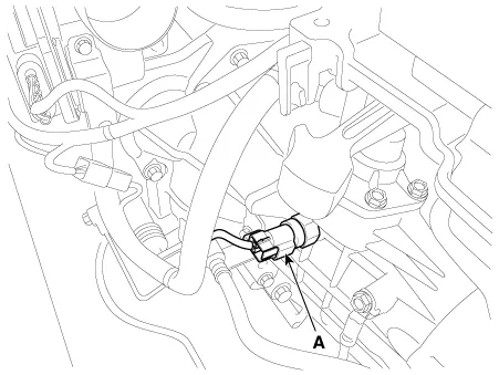
Disconnect the back up lamp switch (A).
|
| 4. |
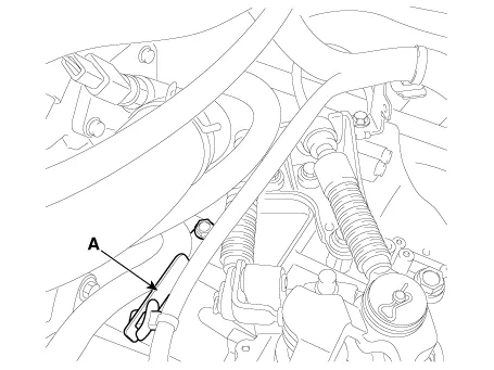
Disconnect the neutral switch connector (A).
|
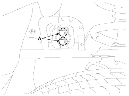
| 5. |
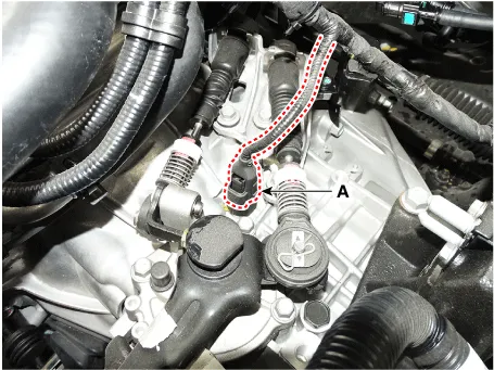
Remove the wiring from the bracket (A).
|
| 6. |
Remove the control cable.
|
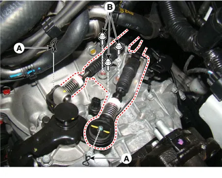
| 7. |
Remove the ground bolt (A) and clutch tube bracket bolt (B).
|
| 8. |
Remove the CKP sensor (A) after removing a bolt.
|
| 9. |
Loosen the starter mounting bolts (A) and the transaxle mounting bolts (B).
|

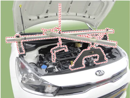
| 10. |
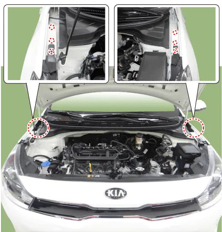
Install the engine support fixture on the engine room.
|
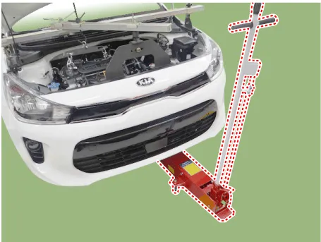
| 11. |
Support the transaxle safely on a jack.
|
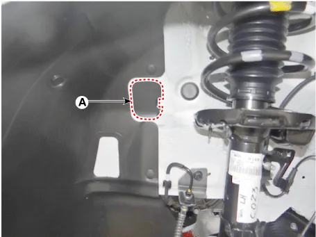
| 12. |
Remove the cover (A).
|
| 13. |
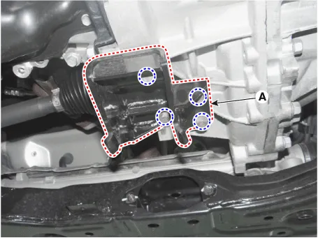
Remove the transaxle mounting bracket bolts (A).
|
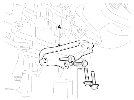
| 14. |
Remove the transaxle support bracket (A).
|

| 15. |
Remove the under cover. (Refer to Engine Mechanical System - "Engine Room Under Cover") |
| 16. |
Remove the drive shaft assembly. (Refer to Driveshaft and Axle - "Front Driveshaft") |
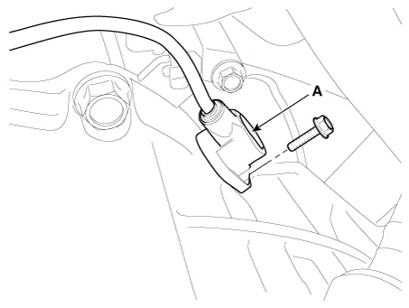
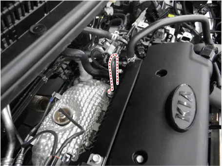
| 17. |
Remove the exhaust manifold stay (A).
|
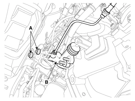
| 18. |
Remove the clutch release cylinder assembly (B) after removing the nuts (A).
|
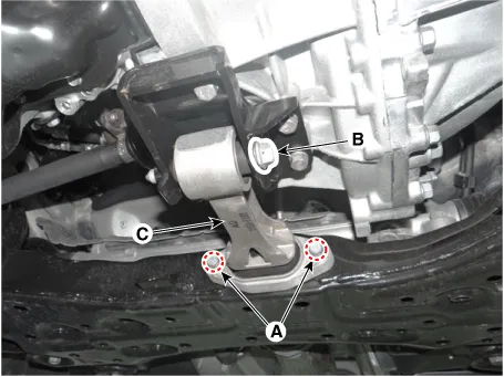
| 19. |
Remove the roll rod bracket (C) after removing bolt (A,B).
|
| 20. |
Remove the roll rod support bracket (A).
|
| 21. |
Support the transaxle safely on a jack. |
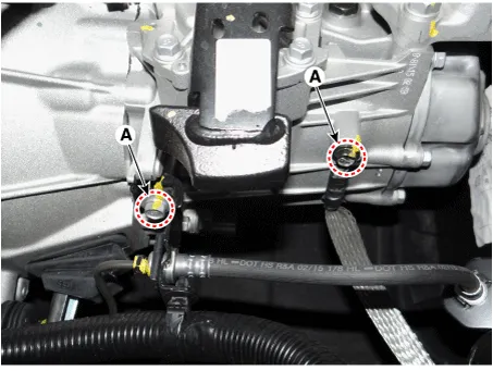
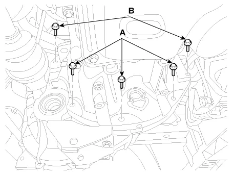
| 22. |
Loosen the transaxle lower mounting bolts (A, B).
|
| 23. |
After separating the transaxle from the engine, remove the transaxle by lowering the jack slowly.
|

| Installation |
In case of oil leakage due to damaged differential oil seal, replace the oil seal with a new one by using special tools (09431-26100, 09231-H1100). |
| 1. |
Install in the reverse order of removal. |
Repair procedures Inspection Manual Transaxle Oil Level Check 1. Stop the engine and then raise the vehicle using the lift.
Specifications Specifications Item Specified Type ON/OFF Operating condition Reverse gear Operating voltage 10V - 15V Operating temperatures -30°C to 100°C [-30°F to 212°F]" Components and components location Component Location 1.
Other information:
Kia Rio 2017-2023 YB Service Manual: Power Window Switch
Components and components location Components Driver Power Window Switch Connector Pin Information [Front / Rear Driver Safety - Auto Up/Down] [LHD] No. Description No. Description 1 Front right power window (Up) 10
Kia Rio 2017-2023 YB Service Manual: Parking Assist Sensor
Components and components location Components Repair procedures Removal 1. Disconnect the negative (-) battery terminal. 2. Remove the rear bumper assembly. (Refer to Body - "Rear Bumper Assembly") 3.
Categories
- Manuals Home
- Kia Rio Owners Manual
- Kia Rio Service Manual
- Coolant
- General Information
- Engine Electrical System
- New on site
- Most important about car
