Kia Rio: Driveshaft Assembly / Dynamic Damper
Components and components location
| Components |
| [RH] |
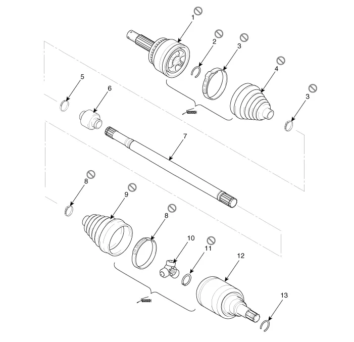
| 1. BJ assembly 2. Clip 3. BJ boot band 4. BJ boot |
5. Dynamic damper band
6. Dynamic damper 7. Shaft 8. TJ boot band |
9. TJ boot
10. Spider assembly 11. Circlip 12. TJ housing |
13. Circlip |
| [LH] |

| 1. BJ assembly 2. BJ circlip 3. BJ boot band 4. BJ boot |
5. Shaft 6. TJ boot band 7. TJ boot 8. Spider assembly |
9. Snap
ring 10. TJ case 11. Circlip |
Repair procedures
| Replacement |
| 1. |
Remove the front driveshaft. (Refer to Driveshaft and axle - “Front Driveshaft”) |
| 2. |
Remove the TJ joint assembly. (Refer to Driveshaft and axle - “TJ joint”) |
| 3. |
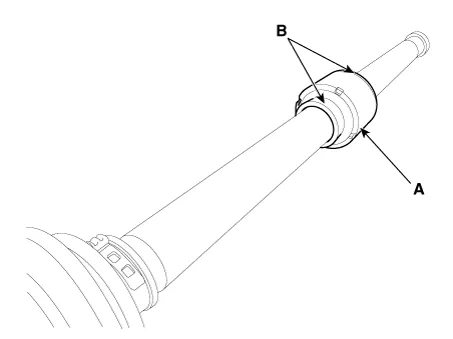
Remove the remove the both side of band (B) of the dynamic damper (A).
|
| 4. |
Fix the driveshaft (A) with a vice (B) as illustrated.
|

| 5. |
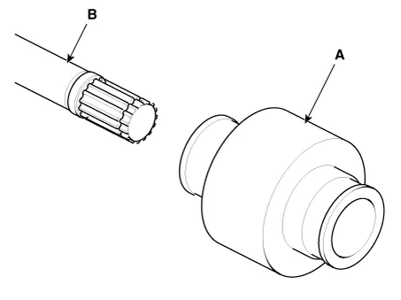
Apply soap powder on the shaft to prevent being damaged between the shaft spline and the dynamic damper when the dynamic damper is removed. |
| 6. |
Seperate the dynamic damper (A) from the shaft (B) carefully.
|
| Installation |
| 1. |
Apply soap powder on the shaft to prevent being damaged between the shaft spline and the dynamic damper. |
| 2. |
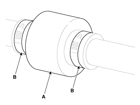
Install the dynamic damper. |
| 3. |
Install the dynamic damper band (A). |
| 4. |
Using the SST(09495-3K000), secure the TJ boot bands (B).
|
| 5. |
Install the TJ joint assembly. (Refer to Driveshaft Assembly - “TJ Joint”) |
| 6. |
Install the front driveshaft. (Refer to Driveshaft Assembly - “Front Driveshaft”) |
| 7. |
Check the front alignment. (Refer to Suspension System - "Alignment") |
Components and components location Components [RH] 1. BJ assembly 2. Clip 3. BJ boot band 4. BJ boot 5.
Components and components location Components [RH] 1. BJ assembly 2. Clip 3. BJ boot band 4. BJ boot 5.
Other information:
Kia Rio 2017-2023 YB Service Manual: Power Door Lock Switch
Repair procedures Removal • When removing with a flat-tip screwdriver or remover, wrap protective tape around the tools to prevent damage to components.
Kia Rio 2017-2023 YB Service Manual: Rear Glass Defogger
C
Categories
- Manuals Home
- Kia Rio Owners Manual
- Kia Rio Service Manual
- Body (Interior and Exterior)
- Engine Control / Fuel System
- Maintenance
- New on site
- Most important about car
