Kia Rio: Cylinder Head Assembly / Cylinder Head
Components and components location
| Components |
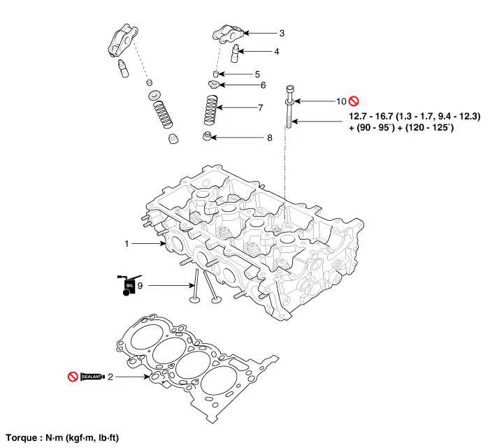
| 1. Cylinder head assembly 2. Cylinder head gasket 3. Swing arm 4. HLA(Hydraulic Lash Adjuster) 5. Retainer lock |
6. Retainer 7. Valve spring 8. Valve stem seal 9. Valve 10. Cylinder head bolt |
Repair procedures
| Removal |
Engine removal is not required for this procedure.
|

|

| 1. |
Remove the engine cover. (Refer to Engine and Transaxle Assembly - "Engine Cover") |
| 2. |
Remove the battery. (Refer to Engine Electrical System - "Battery") |
| 3. |
Remove the engine room under cover. (Refer to Engine and Transaxle Assembly - "Engine Room Under Cover") |
| 4. |
Drain the coolant. (Refer to Cooling System - Coolant") |
| 5. |
Remove the air cleaner assembly. (Refer to Intake and Exhaust System - "Air Cleaner") |
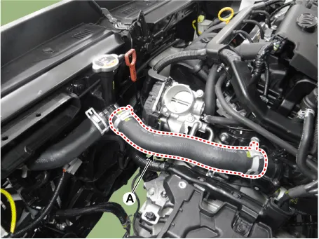
| 6. |
Disconnect the radiator upper hose (A).
|
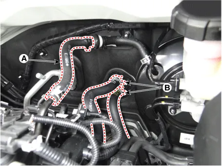
| 7. |
Disconnect the brake booster vacuum hose (A), and heater hoses (B).
|
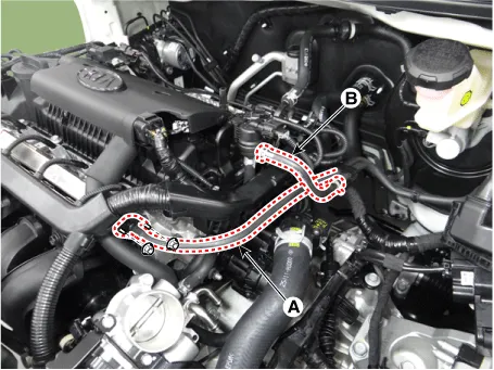
| 8. |
Disconnect the fuel hose (A), purge control solenoid valve (PCSV) hose (B).
|
| 9. |
Remove the water temperature control assembly. (Refer to Cooling System - "Water Temperature Control Assembly") |
| 10. |
Remove the cylinder head cover. (Refer to Cylinder Head Assembly - "Cylinder Head Cover") |
| 11. |
Remove the intake manifold. (Refer to Intake and Exhaust System - "Intake Manifold") |
| 12. |
Remove the delivery pipe assembly. (Refer to Engine Control / Fuel System - "Delivery Pipe") |
| 13. |
Remove the exhaust manifold. (Refer to Intake and Exhaust System - "Exhaust Manifold") |
| 14. |
Remove the timing chain. (Refer to Timing System - "Timing Chain") |
| 15. |
Remove the cvvt & camshaft. (Refer to Cylinder Head Assembly - "CVVT & Camshaft" ) |
| 16. |
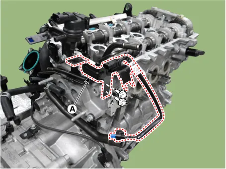
Remove the vacuum pipe (A).
|

| 17. |
Remove the solenoid valve bracket (A).
|
| 18. |
Remove the intake camshaft position sensor (CMPS). (Refer to Engine Control / Fuel System - "Camshaft Position Sensor") |
| 19. |
Remove the exhaust CVVT oil control valve (OCV). |
| 20. |
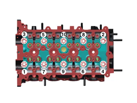
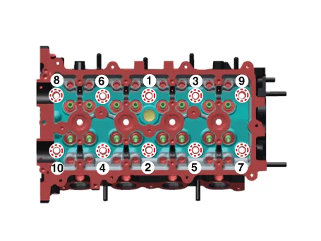
Uniformly loosen and remove the cylinder head bolts, in several passes, in the sequence shown.
|
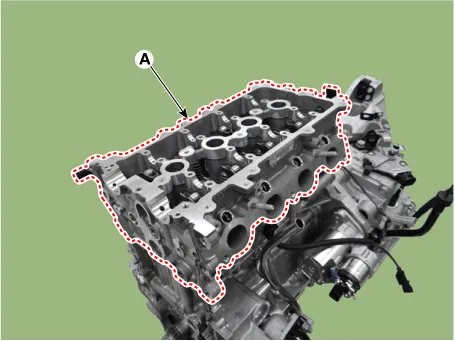
| 21. |
Lift the cylinder head (A) from the dowels on the cylinder block and place the cylinder head on wooden blocks on a bench.
|
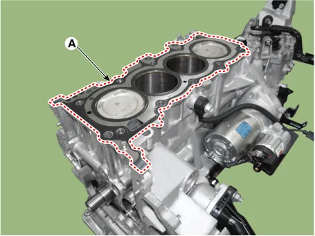
| 22. |
Remove the cylinder head gasket (A).
|
| Disassembly |
| 1. |
Remove the swing arm and the hydraulic lash adjuster assembly (A).
|
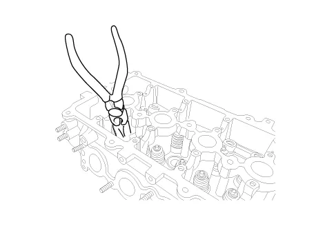
| 2. |
Remove the valves.
|
| Inspection |
Cylinder Head
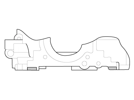
| 1. |
Inspect for flatness. Using a precision straight edge and feeler gauge, measure the surface contacting cylinder block and the manifolds for warpage. If the flatness is greater than maximum, replace the cylinder head.
|

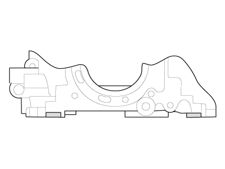
| 2. |
Inspect for cracks. Check the combustion chamber, intake ports, exhaust ports and cylinder block surface for cracks. If cracked, replace the cylinder head. |
Valve And Valve Spring
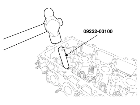
| 1. |
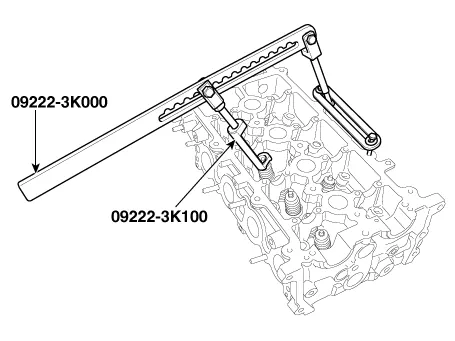
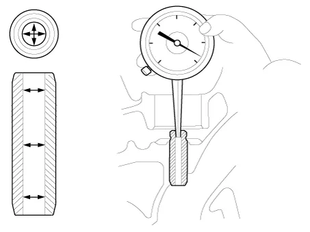
Inspect valve stems and valve guides.
|
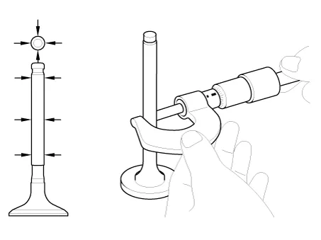
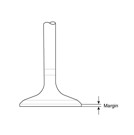
| 2. |
Inspect valves.
|
| 3. |
Inspect valve seats.
|
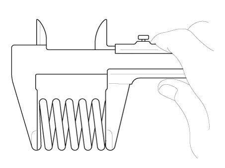
| 4. |
Inspect valve springs.
|
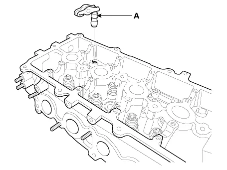
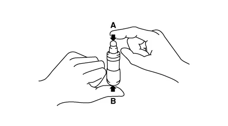
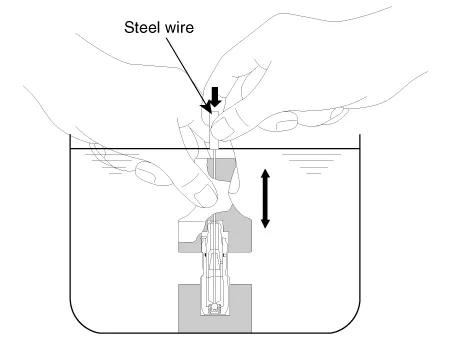
HLA (Hydraulic Lash Adjuster)
With the HLA filled with engine oil, hold A and press B by hand. If B moves, replace the HLA.
|
Problem |
Possible cause |
Action |
|
1. Temporary noise when starting a cold engine |
Normal |
This noise will disappear after the oil in the engine reaches the normal
pressure. |
|
2. Continuous noise when the engine is started after parking more than 48
hours. |
Oil leakage of the high pressure chamber on the HLA, allowing air to get
in. |
Noise will disappear within 15 minutes when engine runs at 2000-3000 rpm.If
it doesn’t disappear, refer to step 7 below. |
|
3. Continuous noise when the engine is first started after rebuilding cylinder
head. |
Insufficient oil in cylinder head oil gallery. |
|
|
4. Continuous noise when the engine is started after excessively cranking
the engine by the starter motor or band. |
Oil leakage of the high-pressure chamber in the HLA, allowing air to get
in.Insufficient oil in the HLA. |
|
|
5. Continuous noise when the engine is running after changing the HLA. |
Do not run engine at a speed higher than 3000 rpm, as this may damage the
HLA. |
|
|
6. Continuous noise during idle after high engine speed. |
Engine oil level too high or too low. |
Check oil level.Drain or add oil as necessary. |
|
Excessive amount of air in the oil at high engine speed. |
Check oil supply system. |
|
|
Deteriorated oil. |
Check oil quality.If deteriorated, replace with specified type. |
|
|
7. Noise continues for more than 15 minutes. |
Low oil pressure. |
Check oil pressure and oil supply system of each part of engine. |
|
Faulty HLA. |
Remove the cylinder head cover and press HLA down by hand.If it moves, replace
the HLA. Be careful with the hot HLAS. |
| Reassembly |
|
| 1. |
Install the valves.
|
| 2. |
Install the swing arm and the hydraulic lash adjuster assembly (A).
|
| Installation |
|
| 1. |
Install the cylinder head gasket.
|
| 2. |
Install the cylinder head assembly.
|
| 3. |
Install the other parts in the reverse order of removal. |
Description and operation Description Continuous Variable Valve Timing (CVVT) system advances or retards the valve timing of the intake and exhaust valve in accordance with the ECM control signal which is calculated by the engine speed and load.
Other information:
Kia Rio 2017-2023 YB Service Manual: Rear Glass Defogger Switch
Repair procedures Inspection 1. In the body electrical system, failure can be quickly diagnosed by using the vehicle diagnostic system (KDS/GDS). The diagnostic system (KDS/GDS) provides the following information. (1) Self diagnosis : Checking failure and code number (DTC)
Kia Rio 2017-2023 YB Service Manual: Heater & A/C Control Unit (FATC)
Components and components location Components Connector Pin Function No. Connector A Connector B 1 Battery ⁻ 2 ISG battery (+) ⁻ 3 Illumination (+) ⁻
Categories
- Manuals Home
- Kia Rio Owners Manual
- Kia Rio Service Manual
- Brake System
- Maintenance Schedule
- Maintenance
- New on site
- Most important about car
