Kia Rio: Steering wheel / Heated Steering wheel
Description and operation
| Description |
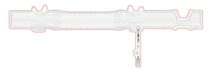
The heated steering wheel system improves the thermal comfort of the driver by heating the steering wheel when manually selected.
Specifications
|
Item |
Specification |
|
Voltage |
13.5 V ± 0.1V, 80W±10% |
|
Heated pad resistance |
1.85 ± 0.2 Ω (at 22°C ±1°C) |
|
NTC resistance |
10.0 kΩ ± 3% (at 23 - 27°C) |
Schematic diagrams
| System Circuit Diagram |
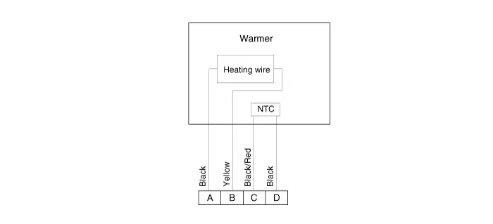
| Harness Connector |

| Terminal Function |
|
Housing |
Pin |
Function |
Wire color |
|
Pad |
A |
GND |
Black |
|
B |
HEATER |
Yellow |
|
|
C |
NTC+ |
Black / Red |
|
|
D |
NTC¯ |
Black |
Repair procedures
| Inspection |
| 1. |
Measure a resistance of NTC and Heated pad. NTC resistance (Black / Red, Black) : 10.0 kΩ ± 3% (at 23 - 27°C) Heated pad resistance (Yellow) : 1.85 ± 0.2 Ω (at 22°C ±1°C) |
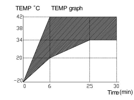
| 2. |
Measure a temperature.
|
Components and components location Components 1. Steering wheel 2. Lower cover 3. Bezel 4. Remote switch 5.
General information General The supplemental restraint system (SRS) is designed to supplement the seat belt to help reduce the risk or severity of injury to the driver and passenger by activating and deploying the driver, passenger, side airbag and belt pretensioner in certain frontal or side collisions.
Other information:
Kia Rio 2017-2023 YB Service Manual: Power Door Locks
Components and components location Component Location 1. Driver power window switch 2. Assist power window switch 3 . Body Comtrol Module (BCM) 4 . Tailgate actuator 5 . Door latch lock actuator 6 .
Kia Rio 2017-2023 YB Service Manual: Heating,Ventilation, Air Conditioning
Specifications Specification Air Conditioner Item Specification Compressor Type DVE12 Oil type & Capacity PAG 30, 120 ± 10 g Displacement 122 cc/rev Expansion valve Type
Categories
- Manuals Home
- Kia Rio Owners Manual
- Kia Rio Service Manual
- Emission Control System
- Body Electrical System
- Suspension System
- New on site
- Most important about car
