Kia Rio: Evaporative Emission Control System / Canister
Repair procedures
| Removal |
| 1. |
Turn the ignition switch OFF and disconnect the battery negative (-) terminal. |
| 2. |
Remove the fuel tank assembly. (Refer to Fuel System - "Fuel Tank") |
| 3. |
Disconnect the vapor hose and quick-connector (A) and ventilation hose (B).
|
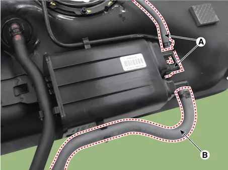
| 4. |
Remove the mounting bolt (A) and then remove the canister.
|

| Inspection |
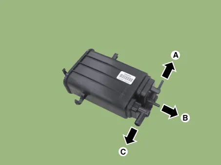
| 1. |
Check for the following items visually.
A: Canister ↔ Fuel Tank B: Canister ↔ Intake Manifold C: Canister ↔ Atmosphere |
| Installation |
| 1. |
Install in the reverse order of removal. |
Description and operation Description Evaporative Emission Control System prevents fuel vapor stored in fuel tank from vaporizing into the atmosphere.
Description and operation Description A ratchet tightening device on the threaded fuel filler cap reduces the chances of incorrect installation, which would seal the fuel filler.
Other information:
Kia Rio 2017-2023 YB Service Manual: Heating,Ventilation, Air Conditioning
Specifications Specification Air Conditioner Item Specification Compressor Type DVE12 Oil type & Capacity PAG 30, 120 ± 10 g Displacement 122 cc/rev Expansion valve Type
Kia Rio 2017-2023 YB Service Manual: Intake Actuator
Description and operation Description The intake actuator is located at the blower unit. It regulates the intake door by signal from control unit. Pressing the intake selection switch will shift between recirculation and fresh air modes.
Categories
- Manuals Home
- Kia Rio Owners Manual
- Kia Rio Service Manual
- General Information
- Body Electrical System
- Cooling System
- New on site
- Most important about car
