Kia Rio: AVN System / AVN(Audio Video Navigation) head unit
Components and components location
| Components |

Connector Pin Information
|
No. |
Connector A |
Connector B |
|
1 |
Rear door left speaker (+) |
- |
|
2 |
Rear door left speaker (-) |
MIC (+) |
|
3 |
- |
- |
|
4 |
- |
- |
|
5 |
- |
Antenna power |
|
6 |
Camera Power |
Illumination (+) |
|
7 |
Camera Video |
Multimedia-CAN (High) |
|
8 |
- |
- |
|
9 |
- |
ALT Left_output (-) |
|
10 |
AUX Audio right_input |
Battery (+) |
|
11 |
AUX Detect |
Battery (+) |
|
12 |
Steering wheel remote controller |
Ground |
|
13 |
Front door left speaker (+) |
Ground |
|
14 |
Front door left speaker (-) |
MIC (Ground) |
|
15 |
Front door right speaker (-) |
MIC (-) |
|
16 |
Front door right speaker (+) |
- |
|
17 |
- |
- |
|
18 |
- |
- |
|
19 |
- |
Illumination (-) |
|
20 |
Camera Power_Ground |
Multimedia-CAN (Low) |
|
21 |
Camera Video_Ground |
- |
|
22 |
- |
ACC |
|
23 |
- |
- |
|
24 |
AUX Audio left_input |
- |
|
25 |
AUX Audio ground |
Reverse |
|
26 |
Steering wheel remote controller (Ground) |
Door open |
|
27 |
Rear door right speaker (-) |
Door unlock_status |
|
28 |
Rear door right speaker (+) |
Manual parking |
|
29 |
- |
'P' Position |
|
30 |
- |
Auto light |
|
31 |
- |
- |
|
32 |
- |
- |
|
33 |
Camera shield_Ground |
IGN1 |
|
34 |
- |
- |
|
35 |
- |
- |
|
36 |
- |
|
|
37 |
- |
|
|
38 |
Vehicle speed |

Repair procedures
| Removal |
|

| 1. |
Disconnect the negative (-) battery terminal. |
| 2. |
Remove the center fascia duct assembly. (Refer to Body - "Center Fascia Panel") |
| 3. |
Remove the AVN head unit (A) after loosening the mounting screws.
|
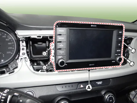
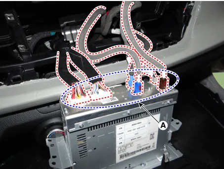
| 4. |
Remove the AVN head unit after disconnecting the connectors and antenna cable (A).
|
| Installation |
| 1. |
Connect the AVN head unit connectors and antenna cable. |
| 2. |
Install the AVN head unit. |
| 3. |
Install the center fascia duct assembly. |
| 4. |
Connect the negative (-) battery terminal. |
|

Components and components location Component Location 1 . AVN head unit 2. Roof antenna (Radio+GPS+DAB) 3 . Multimedia jack 4 .
Repair procedures Inspection Troubleshooting of the speakers When handling the speakers : • Do not cause shock to the speakers by dropping or throwing them.
Other information:
Kia Rio 2017-2023 YB Service Manual: Lane Departure Warning System (LDWS)
Components and components location Components 1. LDWS ON/OFF switch 2. Instrument cluster 3. LDWS unit (MFC) ※ MFC : Multi Function Camera – Function : LDWS, HBA, AEB Description and operation Description System block diagram Components of LDWS
Kia Rio 2017-2023 YB Service Manual: Lighting System
Specifications Specification Item Type Bulb Watt (W) Front Headlamp Halogen Low/High H4 LL 55/60 Turn signal lamp PY21W 21 Position lamp W5W
Categories
- Manuals Home
- Kia Rio Owners Manual
- Kia Rio Service Manual
- Cooling System
- Suspension System
- Body Electrical System
- New on site
- Most important about car
