Kia Rio: Windshield Wiper/Washer / Windshield Wiper-Washer Switch
Repair procedures
| Removal |
| [BCM Type] |
| 1. |
Disconnect the negative (-) battery terminal. |
| 2. |
Remove the steering wheel. (Refer to Steering System - "Steering Wheel") |
| 3. |
Remove the steering column upper and lower shrouds after loosening the screws. (Refer to Body - "Steering Column Shroud Panel") |
| 4. |
Remove the clock spring. (Refer to Restraint - "Driver Airbag (DAB) Module and Clock Spring")
|
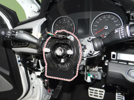
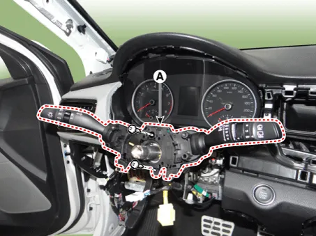
| 5. |
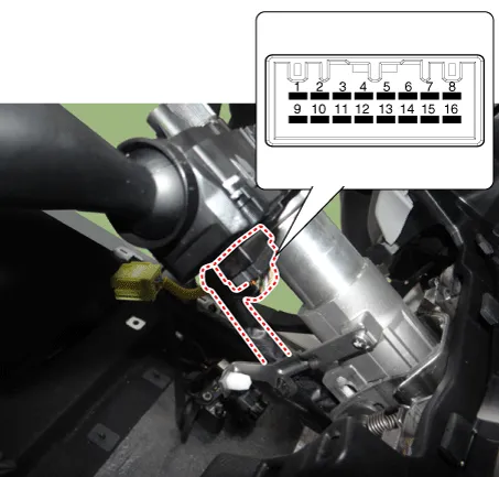
Disconnect the multifunction switch connector (A).
|
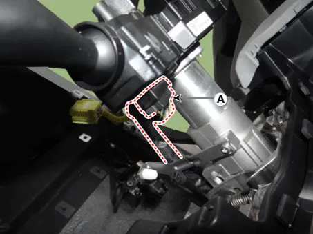
| 6. |
Remove the multifunction switch assembly (A) after loosening the mounting screws.
|
| [Non-BCM Type] |
| 1. |
Disconnect the negative (-) battery terminal. |
| 2. |
Remove the steering column upper and lower shrouds after loosening the screws. (Refer to Body - "Steering Column Shroud Panal") |
| 3. |
Disconnect the wiper switch / washer switch connector (A).
|

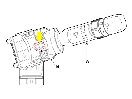
| 4. |
Remove the wiper switch / washer switch (A) by pushing the lock pin (B).
|
| Installation |
| [BCM Type] |
| 1. |
Install the multifunction switch. |
| 2. |
Install the clock spring. |
| 3. |
Install the steering column upper and lower shrouds. |
| 4. |
Install the steering wheel. |
| 5. |
Connect the negative (-) battery terminal. |
| [Non-BCM Type] |
| 1. |
Install the wiper switch / washer switch. |
| 2. |
Connect the wiper switch / washer switch connector. |
| 3. |
Install the steering column upper and lower shrouds. |
| 4. |
Connect the negative (-) battery terminal. |
| Inspection |
Multifunction Switch Inspection
| [BCM Type] |
| 1. |
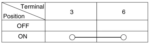
Check for continuity between the terminals in each switch position as shown below.
[Left Handle Drive]
[Right Handle Drive]
|
Inspection (With KDS/GDS)
| 1. |
In the body electrical system, failure can be quickly diagnosed by using the vehicle diagnostic system (KDS/GDS). The diagnostic system(KDS/GDS) provides the following information.
|
| 2. |
Select the 'Car model' and the 'Body Control Module (BCM)' to be checked in order to check the vehicle with the tester. |
| 3. |
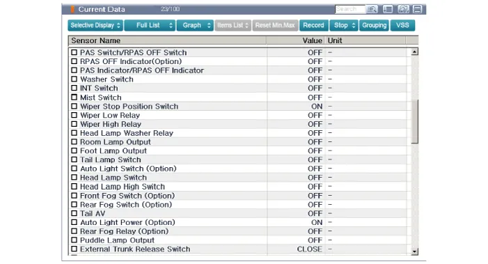
Select the 'Current Data' menu to search the current state of the input/output data.
|
| [Non-BCM Type] |
| 1. |
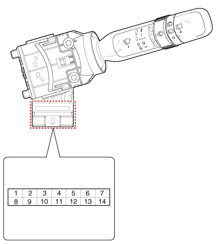
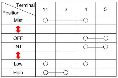
Check for continuity between the terminals in each switch position as shown below.
Front Wiper & Washer Switch [LHD]
[RHD]
Front Washer Switch [LHD]
[RHD]
|


Components and components location Component Location 1. Windshield wiper arm & blade 2. Wiper & washer switch 3.
Components and components location Component Location 1. Cap 2. Nut 3. Wiper arm & blade 4. Cowl top cover 5.
Other information:
Kia Rio 2017-2023 YB Service Manual: Rear Parking Assist System
Specifications Specification Item Specification Ultrasonic sensor Voltage rating DC 12V Detecting range 11.8 - 47.2 in (30 - 120 cm) Operation voltage DC 9 - 16 V Operation current
Kia Rio 2017-2023 YB Service Manual: Smart Key System
Specifications Specifications Smart Key Unit Items Specification Rated voltage DC 12 V Operating voltage DC 9 - 16 V Operating temperature -31 - 167°F (-35 - 75°C) Load Max.
Categories
- Manuals Home
- Kia Rio Owners Manual
- Kia Rio Service Manual
- Heating,Ventilation, Air Conditioning
- Timing Chain
- Brake System
- New on site
- Most important about car
