Kia Rio: Engine Control System / Variable Intake Solenoid (VIS) Valve
Specifications
| Specification |
|
Item |
Specification |
|
Coil resistance (Ω) |
30.0 ~ 35.0 [20°C(68°F)] |
Description and operation
| Description |
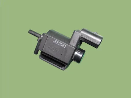
Variable Intake manifold Solenoid (VIS) valve is installed on the intake manifold. The VIS valve controls the vacuum modulator which activates a valve in the intake manifold. The ECM opens or closes this valve according to engine condition (Refer to below table).
|
Engine condition |
VIS valve |
Operation |
|
Medium speed |
Closed |
Increasing engine performance in low engine speed by reducing intake interference
among cylinders |
|
Low / High speed |
Open |
Minimizing intake resistance by shortening intake manifold length and increasing
area of air entrance |

Schematic diagrams
| Circuit Diagram |

Repair procedures
| Inspection |
| 1. |
Turn the ignition switch OFF. |
| 2. |
Disconnect the VIS valve connector. |
| 3. |
Measure resistance between VIS valve terminals 1 and 2.
|
| Removal |
| 1. |
Switch "OFF" the ignition and disconnect the negative (-) battery terminal. |
| 2. |
Remove the air cleaner assembly. (Refer to Engine Mechanical System - "Air Cleaner") |
| 3. |
Remove the electronic throttle body control (ETC) module. (Refer to Engine Control System - "ETC (Electronic throttle body control) System") |
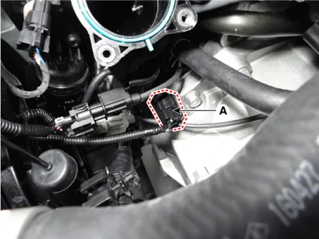
| 4. |
Disconnect the variable intake solenoid valve connector (A).
|
| 5. |
Remove the variable intake solenoid valve (A). |
| 6. |
Disconnect the vacuum hoses (B) from the valve.
|

| 7. |
Remove the variable intake solenoid valve. |
| Installation |
|

| 1. |
Installation is reverse of removal. |
Specifications Specification CVVT Oil Control Valve (OCV) [Bank 1 / Exhaust] Item Specification Coil Resistance (Ω) 6.
Description and operation Description Continuous Variable Valve Timing (CVVT) system advances or retards the valve timing of the intake and exhaust valve in accordance with the ECM control signal which is calculated by the engine speed and load.
Other information:
Kia Rio 2017-2023 YB Service Manual: Rheostat
Components and components location Components Repair procedures Removal 1. Disconnect the negative (-) battery terminal. 2. Remove the crash pad lower panel. (Refer to Body - "Crash Pad Lower Panel") 3.
Kia Rio 2017-2023 YB Service Manual: Power Door Locks
Components and components location Component Location 1. Driver power window switch 2. Assist power window switch 3 . Body Comtrol Module (BCM) 4 . Tailgate actuator 5 . Door latch lock actuator 6 .
Categories
- Manuals Home
- Kia Rio Owners Manual
- Kia Rio Service Manual
- Engine Control / Fuel System
- Battery
- Body (Interior and Exterior)
- New on site
- Most important about car
