Kia Rio: Starting System / Starter
Specifications
| Specification |
▷12V, 1.2kW : ISG only
|
Item |
Specification |
|
|
Rated voltage |
12 V, 1.2 kW |
|
|
The number of pinion teeth |
13 |
|
|
Performance [No-load, 11.5 V] |
Ampere |
Max. 117 A |
|
Speed |
Min. 3,200 rpm |
|
▷12V, 0.9kW : NON- ISG
|
Item |
Specification |
|
|
Rated voltage |
12 V, 0.9 kW |
|
|
The number of pinion teeth |
11 |
|
|
Performance [No-load, 11.5 V] |
Ampere |
Max. 85 A |
|
Speed |
Min. 3,300 rpm |
|
Components and components location
| Components |
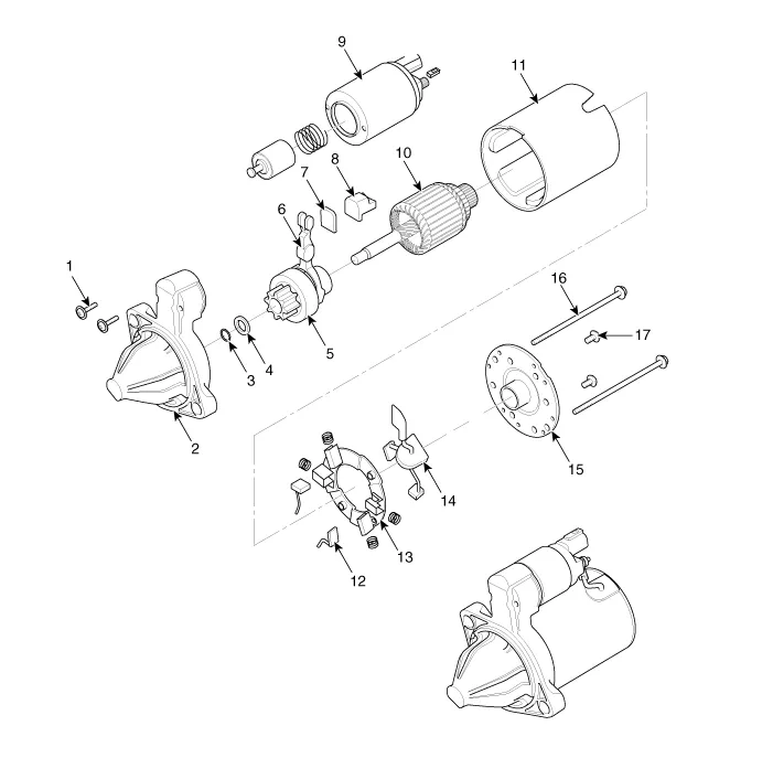
| 1. Screw
2. Front housing 3. Stop ring 4. Stopper 5. Overunn clutch 6. Lever 7. Lever plate 8. Lever packing 9. Magnet switch assembly |
10. Armature
assembly 11. Yoke assembly 12. Brush (-) 13. Brush holder 14. Brush (+) 15. Rear bracket 16. Through bolt 17. Screw |
Description and operation
| Description |
The starting system includes the battery, starter, solenoid switch, ignition switch, inhibitor switch (A/T), clutch pedal switch (M/T), ignition lock switch, connection wires and the battery cable.
When the ignition key is turned to the start position, current flows and energizes the starter motor's solenoid coil.
The solenoid plunger and clutch shift lever are activated, and the clutch pinion engages the ring gear.The contacts close and the starter motor cranks.
In order to prevent damage caused by excessive rotation of the starter armature when the engine starts, the clutch pinion gear overruns.
In conjunction with the ISG function, the starter motor must do a great deal more work. Therefore, the starter motor is configured for a significantly higher number of start cycles. The components of the starter motor have been adapted to the higher requirements.
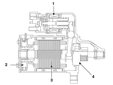
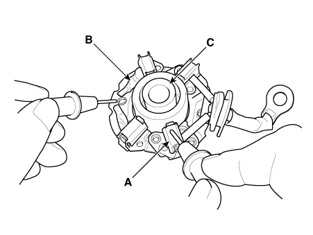
| 1. Solenoid 2. Brush assembly 3. Armature 4. Over runing clutch |
Repair procedures
| Removal |
| 1. |
Turn the ignition switch OFF and disconnect the battery negative (-) terminal. |
| 2. |
Remove the air cleaner. (Refer to Engine Mechanical System - "Air Cleaner") |
| 3. |
Remove the battery. (Refer to Engine Electrical System - "Battery") |
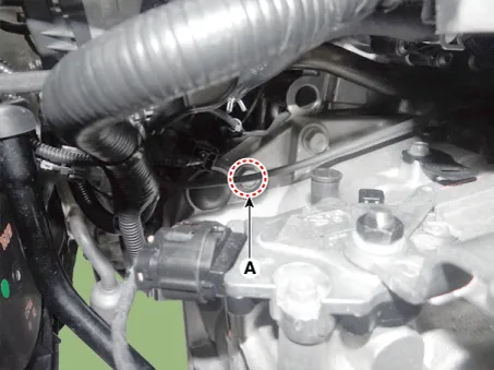
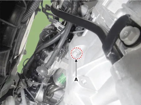
| 4. |
Remove the starter upper bolt (A).
|
| 5. |
Remove the engine room under cover after loosening the mounting bolts. |
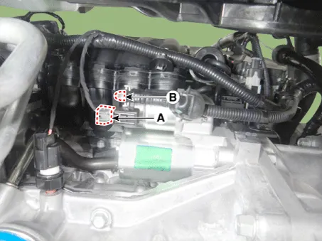
| 6. |
Remove the stater solenoid "B" terminal mounting nut (B), and then disconnect the stater cable and ST connector (A).
|
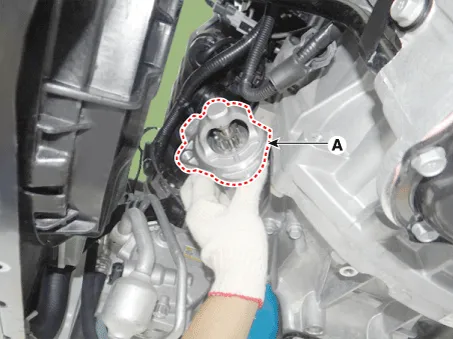
| 7. |
Remove the starter (A) after loosening the mounting lower bolt (B).
|
| 8. |
Remove the starter (A).
|
| Installation |
| 1. |
Install in the reverse order of removal. |
| Inspection |
| Starter Solenoid Inspection |
| 1. |
Disconnect the lead wire from the M-terminal of solenoid switch. |
| 2. |
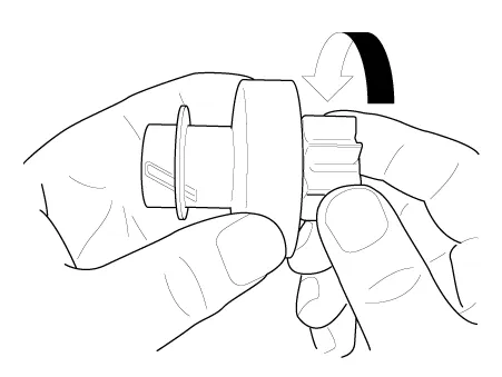
Connect the battery as shown. If the starter pinion pops out, it is working properly.
|


| 3. |
Disconnect the battery from the M terminal. If the pinion does not retract, the hold-in coil is working properly.
|
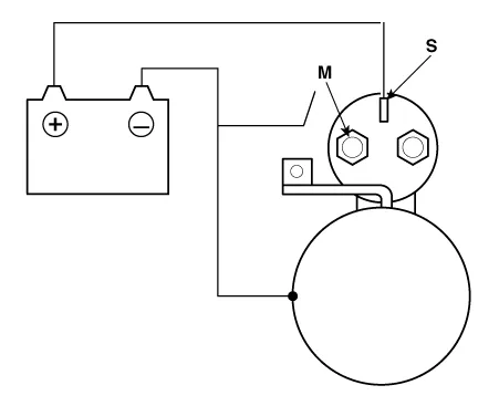
| 4. |
Disconnect the battery also from the body. If the pinion retracts immediately, it is working properly.
|

| Free Running Inspection |
| 5. |
Place the starter motor in a vise equipped with soft jaws and connect a fully-charged 12-volt battery to starter motor as follows. |
| 6. |
Connect a test ammeter (150-ampere scale) and carbon pile rheostats shown is the illustration. |
| 7. |
Connect a voltmeter (15-volt scale) across starter motor.
|

| 8. |
Rotate carbon pile to the off position. |
| 9. |
Connect the battery cable from battery's negative post to the starter motor body. |
| 10. |
Adjust until battery voltage shown on the voltmeter reads 11volts. |
| 11. |
Confirm that the maximum amperage is within the specifications and that the starter motor turns smoothly and freely. |
| Armature |
| 12. |
Remove the starter. |
| 13. |
Disassemble the starter as shown at the beginning of this procedure. |
| 14. |
Inspect the armature for wear or damage from contact with the permanent magnet. If there is wear or damage, replace the armature.
|

| 15. |
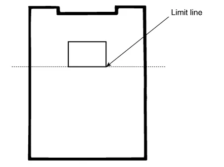
Check the commutator (A) surface. If the surface is dirty or burnt, resurface with emery cloth or a lathe within the following specifications, or recondition with #500 or #600 sandpaper (B).
|
| 16. |
Check the commutator diameter. If the diameter is below the service limit, replace the armature.
|

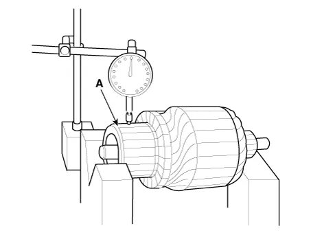
| 17. |
Measure the commutator (A) runout.
|
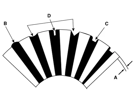
| 18. |
Check the mica depth (A). If the mica is too high (B), undercut the mica with a hacksaw blade to the proper depth. Cut away all the mica (C) between the commutator segments. The undercut should not be too shallow, too narrow, or v-shaped (D).
|
| 19. |
Check for continuity between the segments of the commutator. If an open circuit exists between any segments, replace the armature.
|

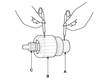
| 20. |
Check with an ohmmeter that no continuity exists between the commutator (A) and armature coil core (B), and between the commutator and armature shaft (C). If continuity exists, replace the armature.
|
| Starter Brush |
| 1. |
Brushes that are worm out, or oil-soaked, should be replaced.
|
| Starter Brush Holder |
| 21. |
Check that there is no continuity between the (+) brush holder (A) and (-) plate (B). If there is continuity, replace the brush holder assembly.
|
| Overrunning Clutch |
| 22. |
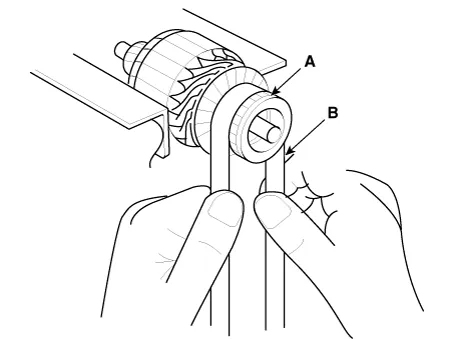
Slide the overrunning clutch along the shaft. Replace it if does not slide smoothly. |
| 23. |
Rotate the overrunning clutch both ways. Does it lock in one direction and rotate smoothly in reverse? If it does not lock in either direction of it locks in both directions, replace it.
|
| 24. |
If the starter drive gear is worn or damaged, replace the overrunning clutch assembly. (the gear is not available separately) Check the condition of the flywheel or torque converter ring gear if the starter drive gear teeth are damaged. |
| Cleaning |
| 1. |
Do not immerse parts in cleaning solvent. Immersing the yoke assembly and/or armature will damage the insulation wipe these parts with a cloth only. |
| 2. |
Do not immerse the drive unit in cleaning solvent. The overrun clutch is pre-lubricated at the factory and sol-vent will wash lubrication from the clutch. |
| 3. |
The drive unit may be cleaned with a brush moistened with cleaning solvent and wiped dry with a cloth. |
Schematic diagrams
| Circuit Diagram |
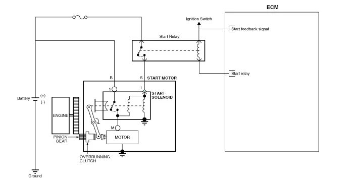
Description and operation Description The starting system includes the battery, starter, solenoid switch, ignition switch, inhibitor switch (A/T), clutch pedal switch (M/T), ignition lock switch, connection wires and the battery cable.
Repair procedures Inspection 1. Turn ignition switch OFF and disconnect the negative (-) battery terminal. 2.
Other information:
Kia Rio 2017-2023 YB Service Manual: Lane Departure Warning System (LDWS)
Components and components location Components 1. LDWS ON/OFF switch 2. Instrument cluster 3. LDWS unit (MFC) ※ MFC : Multi Function Camera – Function : LDWS, HBA, AEB Description and operation Description System block diagram Components of LDWS
Kia Rio 2017-2023 YB Service Manual: Photo Sensor (FATC only)
Description and operation Description The photo sensor is located at the center of defrost nozzles. The photo sensor contains a photovoltaic (sensitive to sunlight) diode. The solar radiation received by its light receiving portion, generates an electromotive force in proportion to the amount of radiation received which is tran
Categories
- Manuals Home
- Kia Rio Owners Manual
- Kia Rio Service Manual
- Motor Driven Power Steering
- General Information
- Coolant
- New on site
- Most important about car
