Kia Rio: Seat Electrical / Seat Heater Switch
Components and components location
| Components |
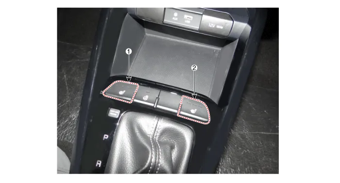
| 1. Driver side seat heater switch
|
2. Passenger side seat heater
switch |
Description and operation
| Description |
Seat Heater Smart Control Technology
| • |
To prevent low temperature burn, seat heater temperature will automatically be lowered after a certain period of time. (Low temperature burn condition: Over 30 minutes at 50°C) |
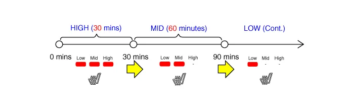
Seat Heater Smart Control Operation
| • |
Change to "MID" after 30 minutes in "HIGH", then "LOW" after 60 minutes in "MID" |
| • |
Change to "LOW" after 60 minutes in "MID" |
|

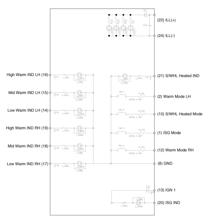
Schematic diagrams
| Circuit Diagram |
Repair procedures
| Removal |
| 1. |
Disconnect the negative (-) battery terminal. |
| 2. |
Remove the front console upper cover. (Refer to Body - "Floor Console Assembly") |
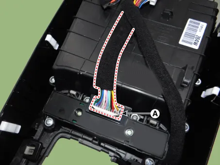
| 3. |
Disconnect the front console upper cover switch connector (A).
|
| 4. |
Remove the front console upper cover switch (A) after loosening the mounting screws.
|

| Installation |
| 1. |
Install the front console upper cover switch. |
| 2. |
Connect the front console upper cover switch connector. |
| 3. |
Install the front console upper cover. |
| 4. |
Connect the negative (-) battery terminal. |
Components and components location Component Location 1. Seat heater unit (Passenger seat only) 2. Front seat back heater 3.
Specifications Specifications Smart Key Unit Items Specification Rated voltage DC 12 V Operating voltage DC 9 - 16 V Operating temperature -31 - 167°F (-35 - 75°C) Load Max.
Other information:
Kia Rio 2017-2023 YB Service Manual: Rear Glass Defogger Printed Heater
Repair procedures Inspection • Wrap tin foil around the end of the voltmeter test lead to prevent damaging the heater line. Apply pressure on the tin foil with hand and move the tin foil along the grid line to check for open circ
Kia Rio 2017-2023 YB Service Manual: Windshield Wiper-Washer Switch
Repair procedures Removal [BCM Type] 1. Disconnect the negative (-) battery terminal. 2. Remove the steering wheel. (Refer to Steering System - "Steering Wheel") 3.
Categories
- Manuals Home
- Kia Rio Owners Manual
- Kia Rio Service Manual
- Maintenance
- Maintenance Schedule
- Engine Control / Fuel System
- New on site
- Most important about car
