Kia Rio: Rear Suspension System / Rear Shock Absorber
Components and components location
| Components |
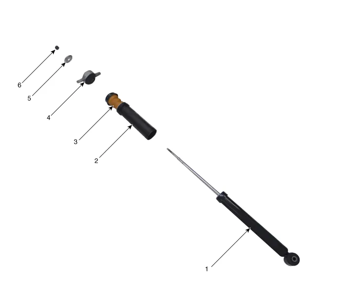
| 1. Shock absorber assembly
2. Dust cover 3. Bumper stopper |
4. Insulator 5. Retainer 6. Lock nut |
Repair procedures
| Removal |
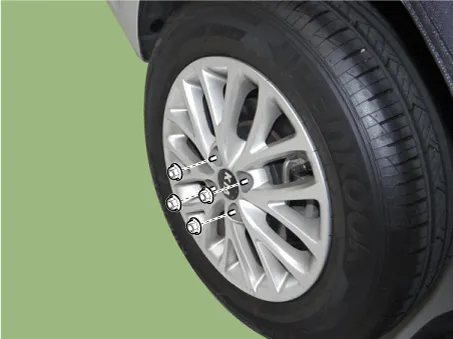
| 1. |
Remove wheel nuts, rear wheel and tire from rear hub.
|

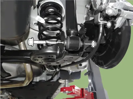
| 2. |
Loosen the shock absorber lower bolt.
|
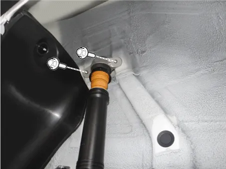
| 3. |
Loosen the bolts and then remove the rear shock apsorber.
|
| 4. |
Install in the reverse order of removal. |
| Inspection |
| 1. |
Check the rubber parts for wear and deterioration. |
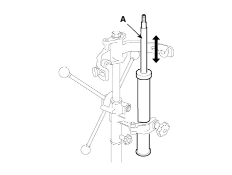
| 2. |
Compress and extend the piston rod (A) and check that there is no abnormal resistance or unusual sound during operation.
|
Disposal
| 1. |
Fully extend the piston rod. |
| 2. |
Drill a hole on the (A) section to remove gas from the cylinder.
|

Components and components location Components [Drum Type] 1. Torsion beam axle 2. Rear spring 3. Rear drum brake disc [Disc Type] 1.
Repair procedures Removal 1. Remove wheel nuts, rear wheel and tire from rear hub. Tightening torque: 107.
Other information:
Kia Rio 2017-2023 YB Service Manual: Rheostat
Components and components location Components Repair procedures Removal 1. Disconnect the negative (-) battery terminal. 2. Remove the crash pad lower panel. (Refer to Body - "Crash Pad Lower Panel") 3.
Kia Rio 2017-2023 YB Service Manual: Front Washer Motor
Repair procedures Inspection Front Washer Motor 1. With the washer motor connected to the reservoir tank, fill the reservoir tank with water. • Before filling the reservoir tank wi
Categories
- Manuals Home
- Kia Rio Owners Manual
- Kia Rio Service Manual
- Body Electrical System
- Features of your vehicle
- Engine Electrical System
- New on site
- Most important about car
