
Kia Rio: Rear Glass Defogger / Rear Glass Defogger Switch
Repair procedures
| Inspection |
| 1. |
In the body electrical system, failure can be quickly diagnosed by using the vehicle diagnostic system (KDS/GDS). The diagnostic system (KDS/GDS) provides the following information.
|
| 2. |
Select the 'Car model' and the 'Body Control Module (BCM)' to be checked in order to check the vehicle with the tester. |
| 3. |
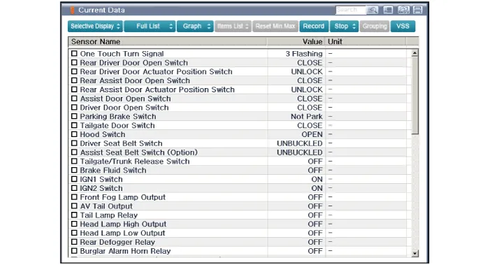
Select the 'Current Data' menu to search the current state of the input/output data.
|
| 4. |
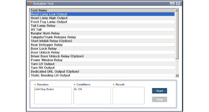
To forcibly actuate the input value of the module to be checked, select option 'Actuation Test'
|
| Removal |
| 1. |
Disconnect the negative (-) battery terminal. |
| 2. |
Remove the heater and A/C controll unit. (Refer to Heating, Ventilation, Air conditioning - "Heater & A/C Control Unit (MANUAL)") (Refer to Heating, Ventilation, Air conditioning - "Heater & A/C Control Unit (FATC)") |
| Installation |
| 1. |
Install the heater and A/C control unit. |
| 2. |
Connect the negative (-) battery terminal. |
Repair procedures Inspection • Wrap tin foil around the end of the voltmeter test lead to prevent damaging the heater line.
Components and components location Component Location 1 . Rear wiper arm & blade 2 . Rear wiper arm nut 3 . Rear wiper grommet 4 .
Other information:
Kia Rio 2017-2023 YB Service Manual: Ignition Switch
Repair procedures Inspection 1. Disconnect the key warning switch connector (A) and ignition switch connector (B) from the steering column. 2. Check for continuity between the terminals.
Kia Rio 2017-2023 YB Service Manual: Lane Departure Warning System (LDWS)
Components and components location Components 1. LDWS ON/OFF switch 2. Instrument cluster 3. LDWS unit (MFC) ※ MFC : Multi Function Camera – Function : LDWS, HBA, AEB Description and operation Description System block diagram Components of LDWS
Categories
- Manuals Home
- Kia Rio Owners Manual
- Kia Rio Service Manual
- Maintenance Schedule
- Suspension System
- Filler-Neck Assembly
- New on site
- Most important about car
