Kia Rio: Body Electrical System / Multifunction Switch
Specifications
| Specifications |
|
Items |
Specifications |
|
|
Rated voltage |
DC 12 V |
|
|
Operating temperature range |
-22 - 176°F (-30 - 80°C) |
|
|
Rated load |
Washer |
Washer : 6A (Motor load) |
Components and components location
| Components |
| [BCM Type] |
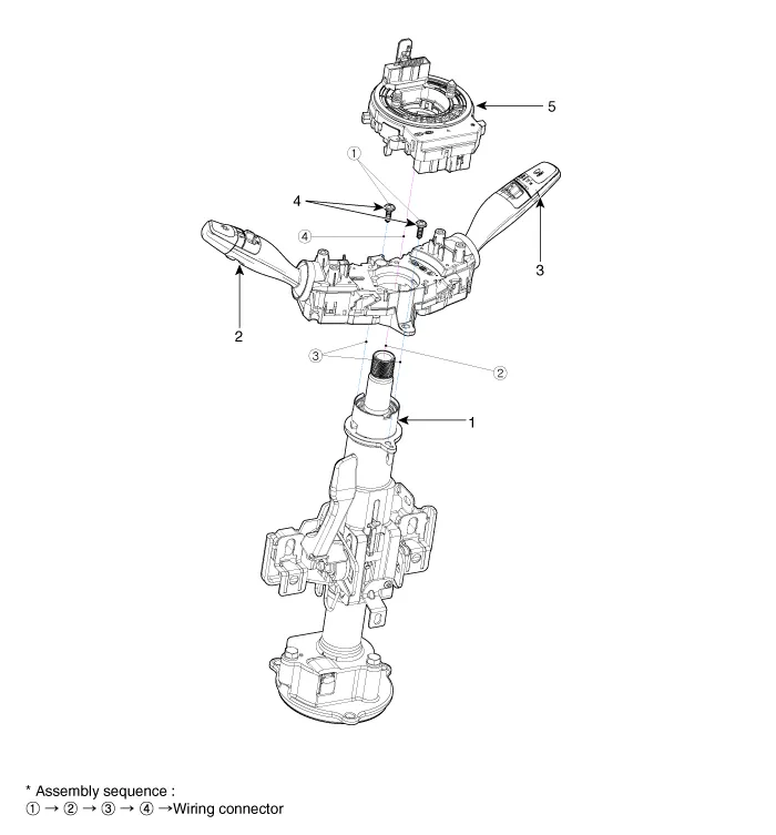
| 1 . Steering column shaft 2 . Lighting switch 3 . Wiper/Washer switch |
4 . Screws 5 . Clock spring |
| [Non -BCM Type] |
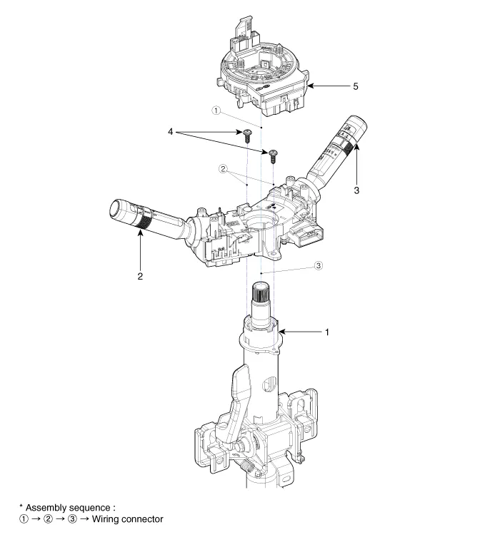
| 1 . Steering column shaft 2 . Lighting switch 3 . Wiper/Washer switch |
4 . Screws 5 . Clock spring |
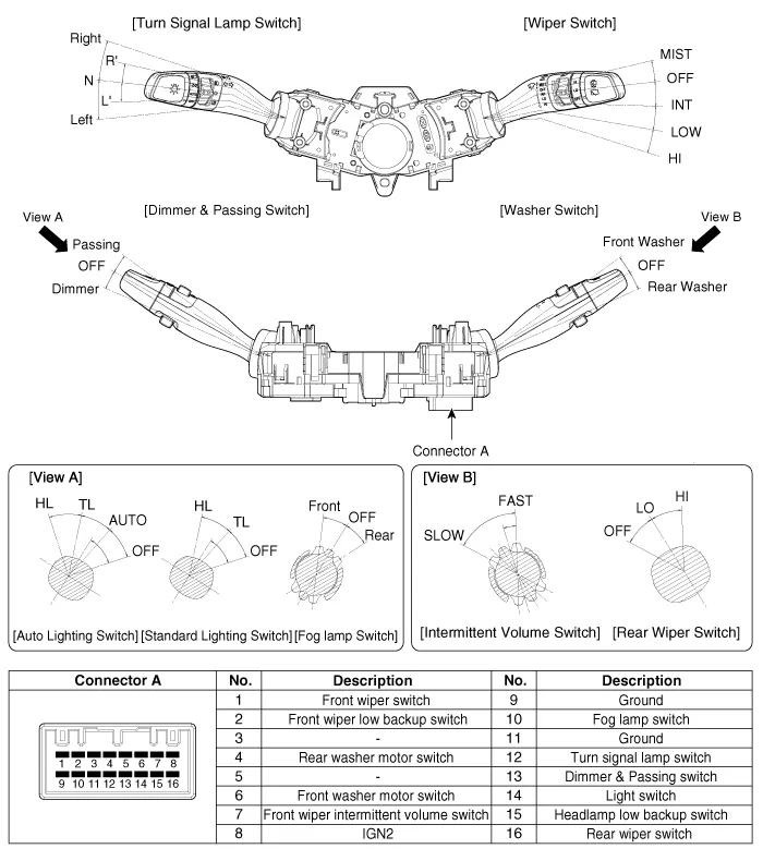
| [BCM Type] |
(LHD)
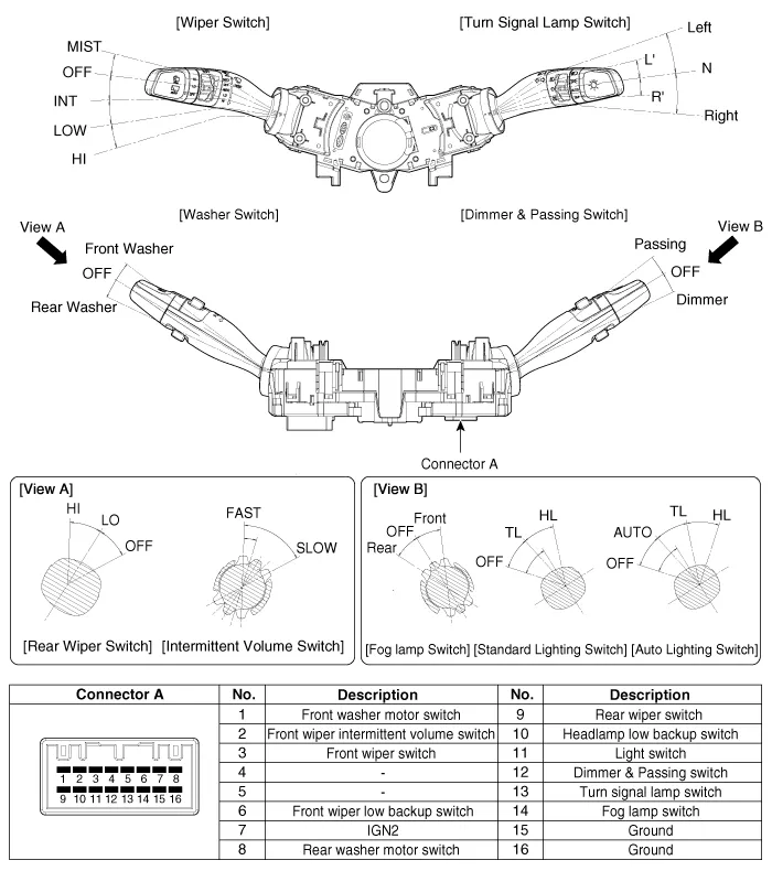
(RHD)
| [Non -BCM Type] |
(LHD)
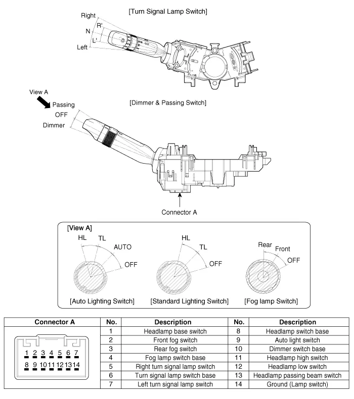
(Turn Signal Lamp Switch / Dimmer & Passing Switch)
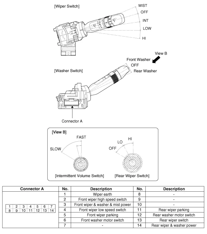
(Wiper Switch / Washer Switch)
(RHD)
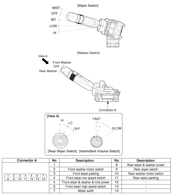
(Wiper Switch / Washer Switch)
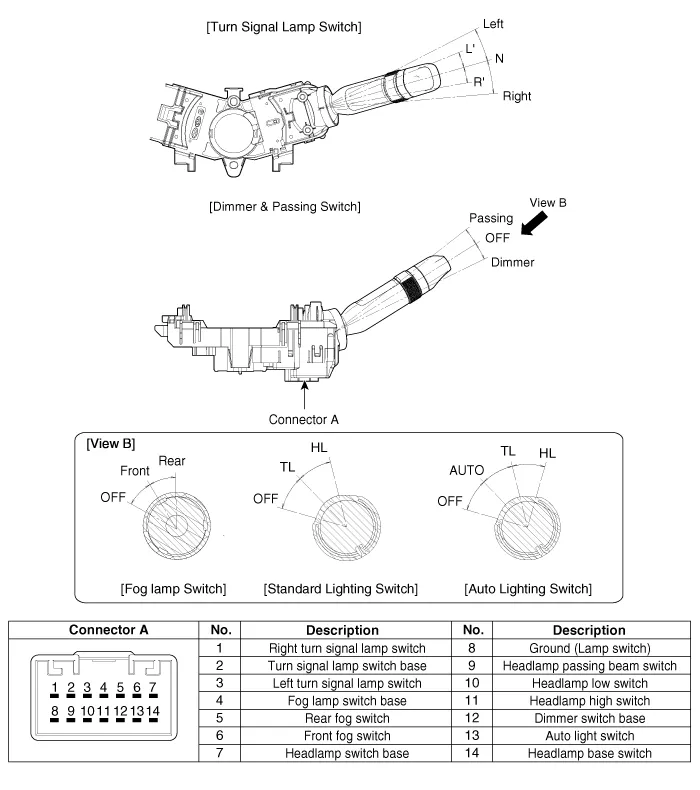
(Turn Signal Lamp Switch / Dimmer & Passing Switch)
Repair procedures
| Removal |
| [BCM Type] |
| 1. |
Disconnect the negative (-) battery terminal. |
| 2. |
Remove the steering wheel. (Refer to Steering System - "Steering Wheel") |
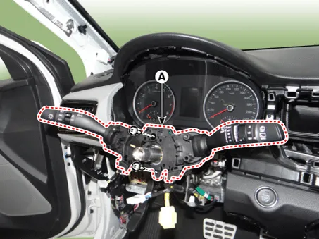
| 3. |
Remove the steering column upper and lower shrouds after loosening the screws. (Refer to Body - "Steering Column Shroud Panal") |
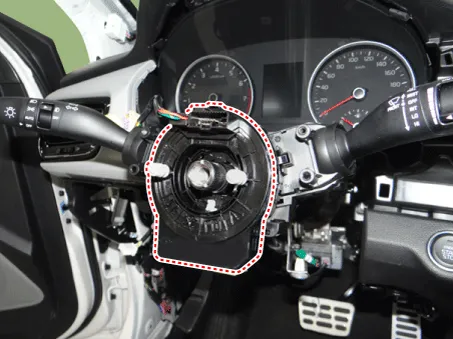
| 4. |
Remove the clock spring. (Refer to Restraint - "Driver Airbag (DAB) Module and Clock Spring")
|

| 5. |
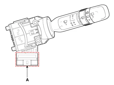
Disconnect the multifunction switch connector (A).
|
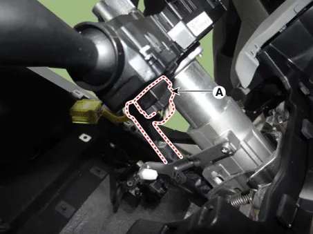
| 6. |
Remove the multifunction switch assembly (A) after loosening the screws.
|
| [Non -BCM Type] |
(LH)
(Turn Signal Lamp Switch / Dimmer & Passing Switch)
| 1. |
Disconnect the negative (-) battery terminal. |
| 2. |
Remove the steering column upper and lower shrouds after loosening the screws. (Refer to Body - "Steering Column Shroud Panal") |
| 3. |
Remove the wiper switch / washer switch. (Refer to Body Electrical System - "Multifunction Switch") |
| 4. |
Remove the steering wheel. (Refer to Steering System - "Steering Wheel") |
| 5. |
Remove the clock spring. (Refer to Restraint - "Driver Airbag (DAB) Module and Clock Spring")
|
| 6. |
Disconnect the turn signal lamp switch / dimmer & passing switch connector (A).
|
| 7. |
Remove the turn signal lamp switch / dimmer & passing switch (A) after loosening the mounting screws.
|

(RH)
(Wiper Switch / Washer Switch)
| 1. |
Disconnect the negative (-) battery terminal. |
| 2. |
Remove the steering column upper and lower shrouds after loosening the screws. (Refer to Body - "Steering Column Shroud Panal") |
| 3. |
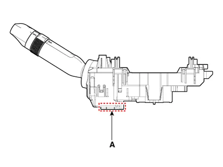
Disconnect the wiper switch / washer switch connector (A).
|
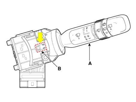
| 4. |
Remove the wiper switch / washer switch (A) by pushing the lock pin (B).
|
| Installation |
| [BCM Type] |
| 1. |
Install the multifunction switch. |
| 2. |
Install the clock spring. |
| 3. |
Install the steering column upper and lower shrouds. |
| 4. |
Install the steering wheel. |
| 5. |
Connect the negative (-) battery terminal. |
| [Non-BCM Type] |
(LH)
(Turn Signal Lamp Switch / Dimmer & Passing Switch)
| 1. |
Install the turn signal lamp switch / dimmer & passing switch. |
| 2. |
Connect the turn signal lamp switch / dimmer & passing switch connector. |
| 3. |
Install the clock spring. |
| 4. |
Install the steering wheel. |
| 5. |
Install the wiper switch / washer switch. |
| 6. |
Install the steering column upper and lower shrouds. |
| 7. |
Connect the negative (-) battery terminal. |
(RH)
(Wiper Switch / Washer Switch)
| 1. |
Install the wiper switch / washer switch. |
| 2. |
Connect the wiper switch / washer switch connector. |
| 3. |
Install the steering column upper and lower shrouds. |
| 4. |
Connect the negative (-) battery terminal. |
| Inspection |
Multifunction Switch Inspection
| [BCM Type] |
| 1. |
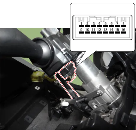
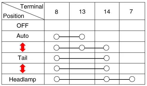
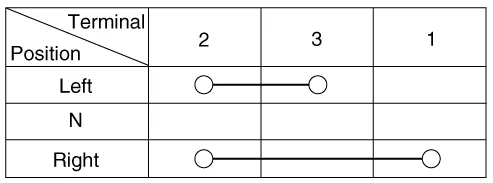
Check for continuity between the terminals in each switch position as shown below.
[Left Handle Drive]
[Right Handle Drive]
|
| [Non -BCM Type] |
(LH)
(Turn Signal Lamp Switch / Dimmer & Passing Switch)
| 1. |
Check for continuity between the terminals in each switch position as shown below.
Lighting switch (Auto light) [LHD]
[RHD]
Lighting Switch (Standard) [LHD]
[RHD]
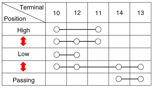
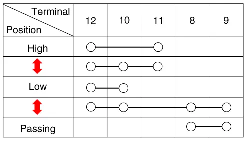
Dimmer And Passing Switch [LHD]
[RHD]
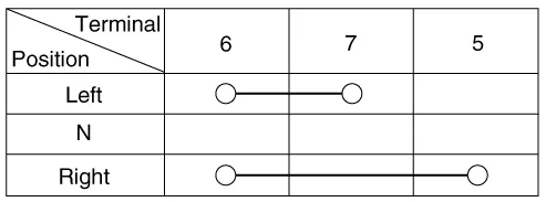
Turn Signal Switch [LHD]
[RHD]
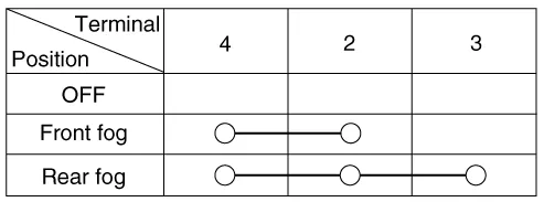
Front/Rear Fog Lamp [LHD]
[RHD]
|


(RH)
(Wiper Switch / Washer Switch)
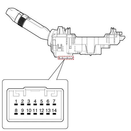
| 1. |
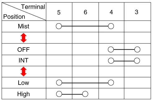
Check for continuity between the terminals in each switch position as shown below.
Front Wiper & Washer Switch [LHD]
[RHD]
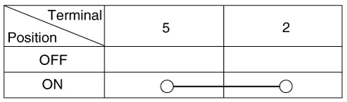
Front Washer Switch [LHD]
[RHD]
Rear Wiper & Washer Switch [LHD]
[RHD]
|


Inspection (With KDS/GDS)
| [BCM Type Only] |
| 1. |
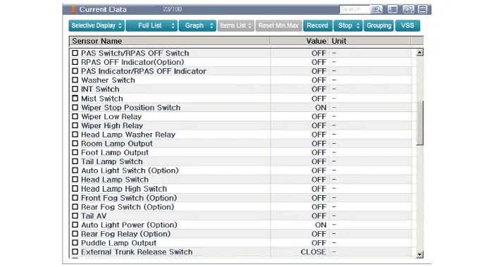
In the body electrical system, failure can be quickly diagnosed by using the vehicle diagnostic system (KDS/GDS). The diagnostic system(KDS/GDS) provides the following information.
|
| 2. |
Select the 'Car model' and the 'Body Control Module (BCM)' to be checked in order to check the vehicle with the tester. |
| 3. |
Select the 'Current Data' menu to search the current state of the input/output data.
|
Repair procedures Removal Rear Combination Lamp (Outside) 1. Disconnect the negative (-) battery terminal. 2.
Components and components location Component Location 1. Driver power window switch 2. Assist power window switch 3 .
Other information:
Kia Rio 2017-2023 YB Service Manual: Indicators And Gauges
Troubleshooting Troubleshooting Error Item Failure symptom Inspection items Detailed inspections Relevant Parts/ Components Screen display LCD screen does not turn on 1) Connector attachments
Kia Rio 2017-2023 YB Service Manual: Compressor
Description and operation Description The compressor is the power unit of the A/C system. It is located on the side of engine block and driven by a V-belt of engine. The compressor changes the low pressure and low temperature refrigerant gas into the high pressure and high temperature refrigerant gas.
Categories
- Manuals Home
- Kia Rio Owners Manual
- Kia Rio Service Manual
- Clutch System
- Steering System
- Emission Control System
- New on site
- Most important about car
