Kia Rio: Manual Transaxle System / Manual Transaxle
Components and components location
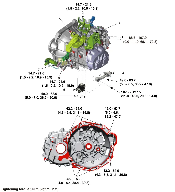
| Components |
|
1. Control shaft complete 2. Control cable bracket 3. Transaxle support bracket 4. Roll rod bracket |
5. Roll rod support bracket 6. Clutch tube bracket 7. Clutch release cylinder assembly |
Repair procedures
| Removal |
| 1. |
Remove the air cleaner assembly. (Refer to Engine Mechanical System - "Air Cleaner") |
| 2. |
Remove the battery and battery tray. (Refer to Engine Electrical System - "Battery") |
| 3. |
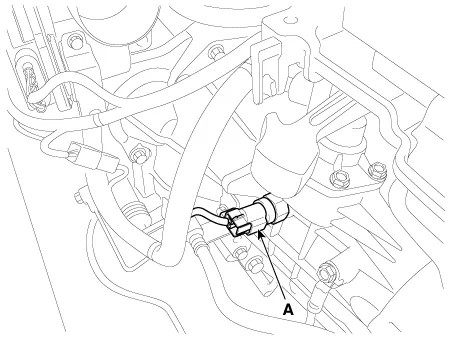
Disconnect the back up lamp switch (A).
|
| 4. |
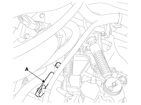
Disconnect the neutral switch connector (A).
|
| 5. |
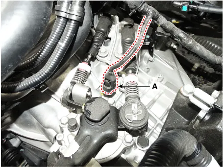
Remove the wiring from the bracket (A).
|
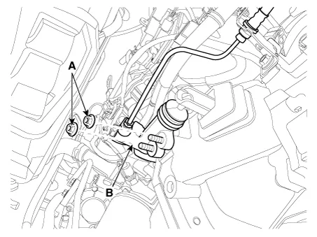
| 6. |
Remove the control cable.
|
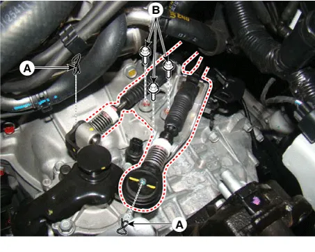
| 7. |
Remove the ground bolt (A) and clutch tube bracket bolt (B).
|
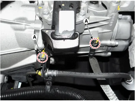
| 8. |
Remove the CKP sensor (A) after removing a bolt.
|
| 9. |
Loosen the starter mounting bolts (A) and the transaxle mounting bolts (B).
|

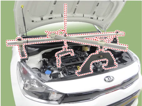
| 10. |
Install the engine support fixture on the engine room.
|
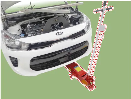
| 11. |
Support the transaxle safely on a jack.
|
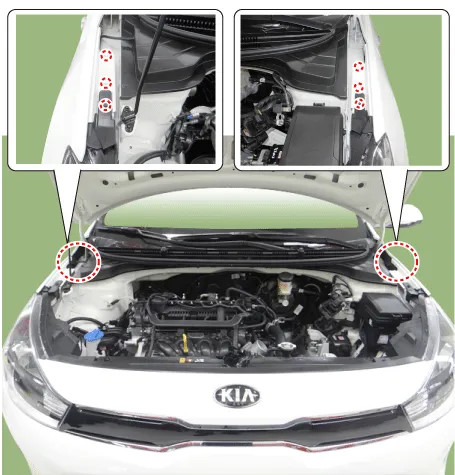
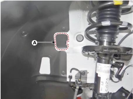
| 12. |
Remove the cover (A).
|
| 13. |
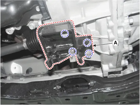
Remove the transaxle mounting bracket bolts (A).
|
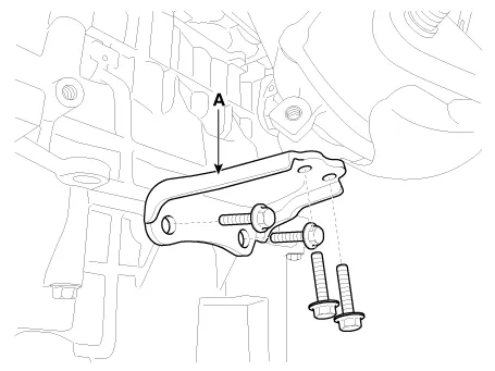
| 14. |
Remove the transaxle support bracket (A).
|

| 15. |
Remove the under cover. (Refer to Engine Mechanical System - "Engine Room Under Cover") |
| 16. |
Remove the drive shaft assembly. (Refer to Driveshaft and Axle - "Front Driveshaft") |
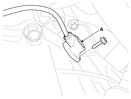
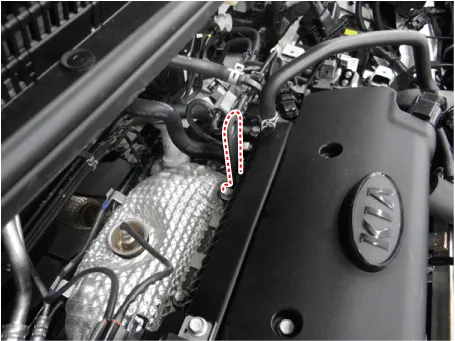
| 17. |
Remove the exhaust manifold stay (A).
|
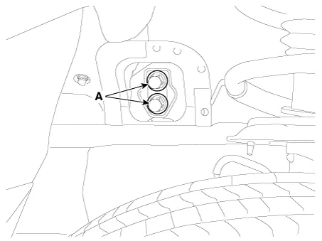
| 18. |
Remove the clutch release cylinder assembly (B) after removing the nuts (A).
|
| 19. |
Remove the roll rod bracket (C) after removing bolt (A,B).
|
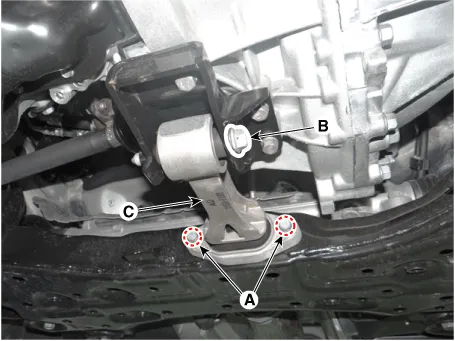
| 20. |
Remove the roll rod support bracket (A).
|
| 21. |
Support the transaxle safely on a jack. |
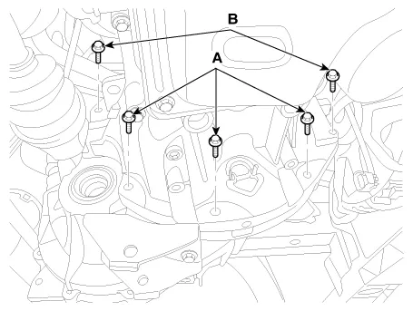
| 22. |
Loosen the transaxle lower mounting bolts (A, B).
|
| 23. |
After separating the transaxle from the engine, remove the transaxle by lowering the jack slowly.
|

| Installation |
In case of oil leakage due to damaged differential oil seal, replace the oil seal with a new one by using special tools (09431-26100, 09231-H1100). |
| 1. |
Install in the reverse order of removal. |
Repair procedures Inspection Manual Transaxle Oil Level Check 1. Stop the engine and then raise the vehicle using the lift.
Specifications Specifications Item Specified Type ON/OFF Operating condition Reverse gear Operating voltage 10V - 15V Operating temperatures -30°C to 100°C [-30°F to 212°F]" Components and components location Component Location 1.
Other information:
Kia Rio 2017-2023 YB Service Manual: Photo Sensor (FATC only)
Description and operation Description The photo sensor is located at the center of defrost nozzles. The photo sensor contains a photovoltaic (sensitive to sunlight) diode. The solar radiation received by its light receiving portion, generates an electromotive force in proportion to the amount of radiation received which is tran
Kia Rio 2017-2023 YB Service Manual: Blower Motor
Repair procedures Inspection 1. Connect the battery voltage and check the blower motor rotation. 2. If the blower motor does not operate well, substitute with a known-good blower motor and check for proper operation.
Categories
- Manuals Home
- Kia Rio Owners Manual
- Kia Rio Service Manual
- Motor Driven Power Steering
- Body Control Module (BCM)
- Timing Chain
- New on site
- Most important about car
