Kia Rio: Hydraulic System / 24 Brake Control Solenoid Valve (PCSV-B)
Specifications
| Specification |
|
Item |
Specification |
|
Type |
Normal open |
|
Input voltage |
12 V |
|
Coil resistance |
3.5 ± 0.2 Ω (at 25°C, 77°F) |
|
Frequency |
50 Hz |
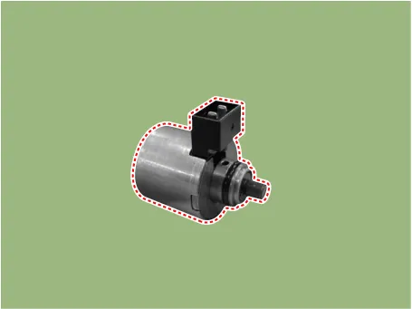
Components and components location
| Component Location |
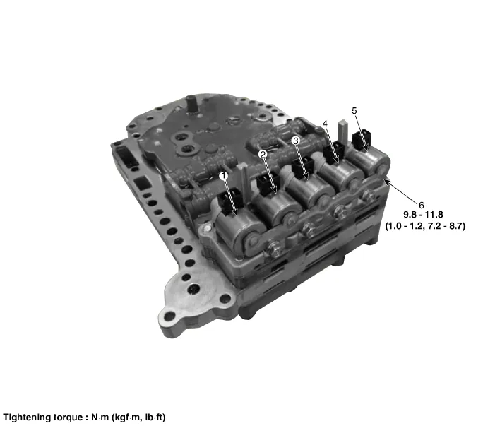
| 1. Overdrive clutch control solenoid
valve (PCSV-A) 2. ON/OFF solenoid valve (SCSV-A) 3. Torque converter control solenoid valve (PCSV-D) |
4. Underdrive clutch control
solenoid valve (PCSV-C) 5. 24 brake control solenoid valve (PCSV-B) 6. Solenoid valve support bracket |
Description and operation
| Description |
| • |
24 brake control solenoid valve is a PWM (Pulse Width Modulation) type. |
| • |
When TCM supplies current to solenoid valve, hydraulic pressure of 24 brake is controlled by solenoid valve.
|
Solenoid valve operation table
|
Range |
PCSV-B |
|
N, P |
● |
|
1 |
● |
|
2 |
|
|
3 |
● |
|
4 |
|
|
R |
|
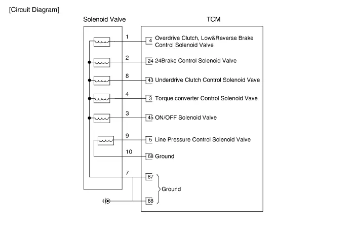
Schematic diagrams
| Circuit Diagram |
Repair procedures
| Inspection |
| 1. |
Switch "OFF" ignition. |
| 2. |
Remove the air cleaner. (Refer to Engine Mechanical System - "Air cleaner") |
| 3. |
Disconnect the main connector (A).
|
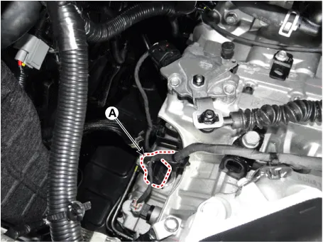
| 4. |
Measure the resistance between ground terminal (7) and signal terminal (2).
|
| Removal |
| 1. |
Remove the valve body assembly (Refer to Hydraulic System - "Valve Body") |
| 2. |
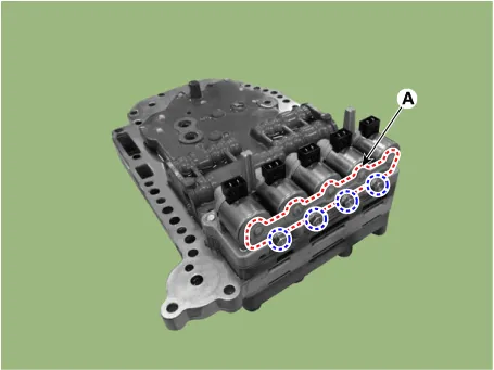
Disconnect the main harness (A).
|
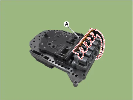
| 3. |
Remove solenoid valve support bracket (A) after loosening the bolts.
|
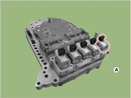
| 4. |
Remove the 24 brake control solenoid valve (A).
|
| Installation |
| 1. |
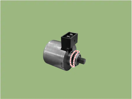
Install in the reverse order of removal. |
When installing, apply the ATF or petroleum jelly to the O-ring to prevent damage.
|

Specifications Specification Item Specification Type Normal open Input voltage 12 V Coil resistance 3.
Specifications Specification Item Specification Type Normal open Input voltage 12 V Coil resistance 3.
Other information:
Kia Rio 2017-2023 YB Service Manual: Indicators And Gauges
Troubleshooting Troubleshooting Error Item Failure symptom Inspection items Detailed inspections Relevant Parts/ Components Screen display LCD screen does not turn on 1) Connector attachments
Kia Rio 2017-2023 YB Service Manual: Power Mosfet (FATC)
Repair procedures Inspection 1. Turn the ignition switch ON. 2. Manually operate the control switch and measure the voltage of blower motor. 3. Select the control switch to raise voltage until high speed.
Categories
- Manuals Home
- Kia Rio Owners Manual
- Kia Rio Service Manual
- Cooling System
- Suspension System
- Clutch System
- New on site
- Most important about car
