Kia Rio: Intake And Exhaust System / Intake Manifold
Components and components location
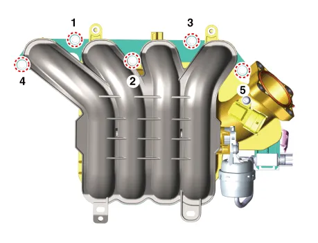
| Components |

| 1. Intake manifold 2. Intake manifold gasket 3. Positive crankcase ventilation (PCV) hose |
4. Purge control solenoid valve
(PCSV) hose 5. Manifold absolute pressure sensor (MAPS) |
Repair procedures
| Removal and Installation |
| 1. |
Disconnect the battery negative terminal. |
| 2. |
Remove the air cleaner assembly. (Refer to Intake and Exhaust System - "Air Cleaner") |
| 3. |
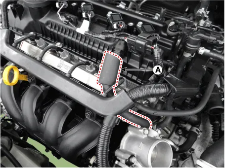
Disconnect the wiring connectors and harness clamps and remove the connector brackets around the intake manifold.
|

| 4. |
Unfasten the electronic throttle body control (ETC) module bolts. (Refer to Engine Control/Fuel System - "ETC (Electronic throttle body control) System") |
| 5. |
Disconnect the positive crankcase ventilation (PCV) hose (A).
|
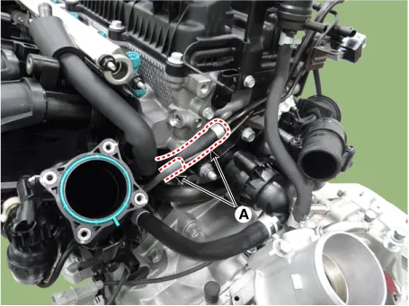
| 6. |
Disconnect the vacuum hose (A).
|
| 7. |
Remove the oilv level gauge. (Refer to Lubrication System -"Oil Level Gauge & Pipe") |
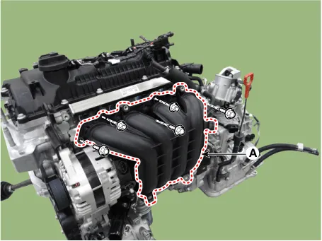
| 8. |
Remove the intake manifold (A).
|

| 9. |
Installation is reverse order of removal. |
Components and components location Comoinents 1. Air intake shield 2. Heat shield 3. Air duct 4. Duct extension 5.
Components and components location Components 1. Exhaust manifold gasket 2. Exhaust manifold 3. Exhaust manifold stay 4.
Other information:
Kia Rio 2017-2023 YB Service Manual: Antenna Coil
Repair procedures Removal 1. Disconnect the negative (-) battery terminal. 2. Remove the crash pad lower panel. (Refer to Body - "Crash Pad Lower Panel") 3. Remove the steering column upper and lower shroud panel.
Kia Rio 2017-2023 YB Service Manual: Multifunction Switch
Specifications Specifications Items Specifications Rated voltage DC 12 V Operating temperature range -22 - 176°F (-30 - 80°C) Rated load Washer Washer : 6A (Motor load) Components and components
Categories
- Manuals Home
- Kia Rio Owners Manual
- Kia Rio Service Manual
- Timing Chain
- Drive Belt
- Maintenance
- New on site
- Most important about car
