
Kia Rio: Intake And Exhaust System / Exhaust Manifold
Components and components location
| Components |

| 1. Exhaust manifold gasket
2. Exhaust manifold |
3. Exhaust manifold stay 4. Heat protector |
Repair procedures
| Removal and Installation |
| 1. |
Disconnect the negative battery terminal. |
| 2. |
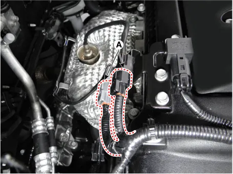
Disconnect the oxygen sensor connector (A).
|
| 3. |
Remove the front muffler. (Refer to Intake And Exhaust System - "Muffler") |
| 4. |
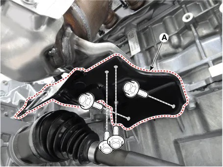
Remove the exhaust manifold stay (A).
|
| 5. |
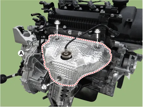
Remove the heat protector (A).
|
| 6. |
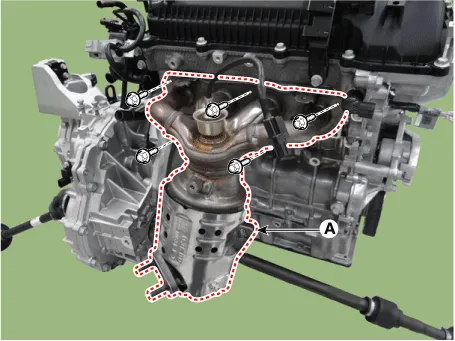
Remove the exhaust manifold (A).
|
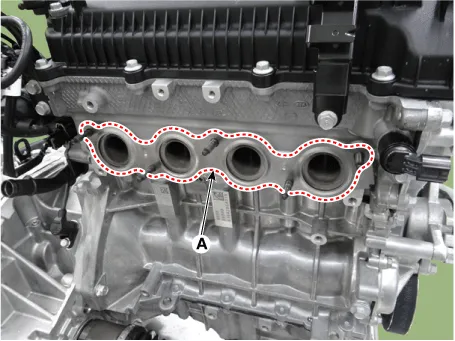
| 7. |
Remove the exhaust manifold gasket (A).
|
| 8. |
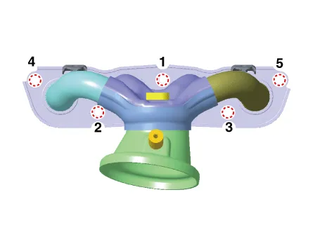
Install in the reverse order of removal.
|

Components and components location Components 1. Intake manifold 2. Intake manifold gasket 3. Positive crankcase ventilation (PCV) hose 4.
Repair procedures Removal and Installation Front Muffler 1. Disconnect the rear oxygen sensor (A). 2.
Other information:
Kia Rio 2017-2023 YB Service Manual: Keyless Entry And Burglar Alarm
Specifications Specification Item Specification Power source 3 V Operating temperature -22 - 176°F (-30 - 80°C) RF Modulation FSK LF Modulation ASK RF frequency
Kia Rio 2017-2023 YB Service Manual: Intake Actuator
Description and operation Description The intake actuator is located at the blower unit. It regulates the intake door by signal from control unit. Pressing the intake selection switch will shift between recirculation and fresh air modes.
Categories
- Manuals Home
- Kia Rio Owners Manual
- Kia Rio Service Manual
- Normal Condition
- Brake System
- Engine Oil and Filter
- New on site
- Most important about car
