Kia Rio: Automatic Transaxle Control System / Input Speed Sensor
Specifications
| Specification |
|
Item |
Specification |
|
Type |
Hall effect sensor |
|
Current |
22 mA (Max) |
|
Output voltage |
High : 4.8 V - 5.2 V |
|
Low : Below 0.8 |
Description and operation
| Description |
| • |
Measures the rate of rotation of the input shaft inside the transaxle and delivers the readings to the TCM. |
| • |
The sensor provides critical input data used in feedback control, torque converter clutch control, gear setting control, line pressure control, clutch activation pressure control, and sensor fault analysis.
|
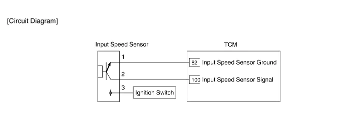
Schematic diagrams
| Circuit Diagram |
Repair procedures
| Inspection |
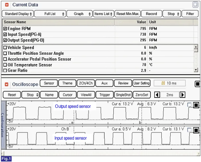
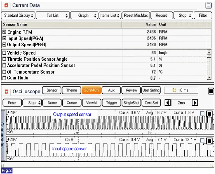
| 1. |
Check the signal waveform of input speed sensor using the KDS/GDS. |
Low speed
High speed
| Removal |
| 1. |
Remove the air cleaner. (Refer to Engine Mechanical System - "Air cleaner") |
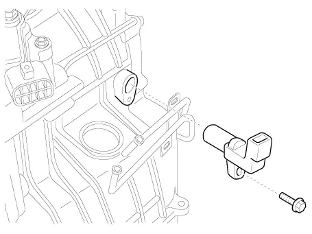
| 2. |
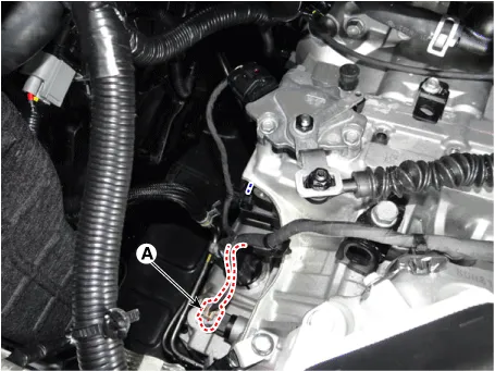
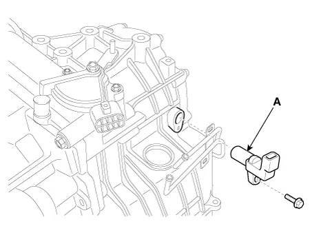
Disconnect the input speed sensor connector (A).
|
| 3. |
Remove the input speed sensor (A) after loosening the bolt.
|
| Installation |
| 1. |
Install in the reverse order of removal. |
Specifications Specification Item Specification Type *NTC thermistor Temp.
Specifications Specification Item Specification Type Hall effect sensor Current 22 mA (Max) Output voltage High : 4.
Other information:
Kia Rio 2017-2023 YB Service Manual: Seat Heater
Components and components location Component Location 1. Seat heater unit (Passenger seat only) 2. Front seat back heater 3. Front seat cushion heater Schematic diagrams Circuit Diagram Repair procedures Inspection 1.
Kia Rio 2017-2023 YB Service Manual: Condenser
Repair procedures Inspection 1. Check the condenser fins for clogging and damage. If clogged, clean them with water, and blow them with compressed air. If bent, gently bend them using a screwdriver or pliers. 2.
Categories
- Manuals Home
- Kia Rio Owners Manual
- Kia Rio Service Manual
- Engine Mechanical System
- Brake System
- Cooling System
- New on site
- Most important about car
