Kia Rio: Ignition System / Ignition Coil
Specifications
| Specification |
|
Item |
Specification |
|
Rated Voltage (V) |
12 |
|
Operation Voltage (V) |
5 - 16 |
|
Item |
Specification |
|||||
|
Engine Speed (RPM) |
1000 |
2000 |
3000 |
4000 |
5000 |
6000 |
|
Dwell Time (ms) |
3.82 |
2.61 |
2.27 |
1.93 |
1.79 |
1.6 |
|
Secondary Coil Voltage (kV) |
32 ↑ |
32 ↑ |
31 ↑ |
30 ↑ |
29 ↑ |
27 ↑ |
Description and operation
| Description |
An ignition coil is an induction coil in an engine's ignition system which transforms the battery's low voltage to the high voltage needed to create an electric spark in the spark plugs to ignite the fuel. Coils have an internal resistor while others rely on a resistor wire or an external resistor to limit the current flowing into the coil from the battery 12 V supply.
Schematic diagrams
| Circuit Diagram |
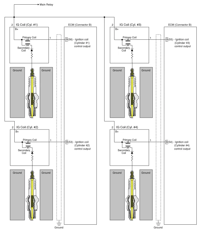
| Connector View |

Repair procedures
| Removal |
| 1. |
Disconnect the battery nagative terminal. |
| 2. |
Remove the engine cover. |
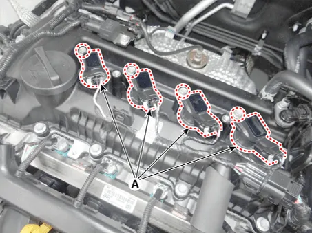
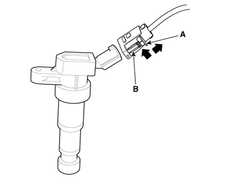
| 3. |
Remove the ignition coil (A) after loosening the mounting bolts.
|

| Installation |
| 1. |
Install in the reverse order of removal. |
| Inspection |
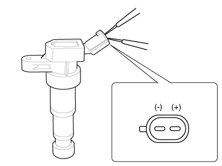
| 1. |
Measure the primary coil resistance between terminal 1 and 2.
|
Description and operation Description Ignition timing is controlled by the electronic control ignition timing system. The standard reference ignition timing data for the engine operating conditions are pre-pro grammed in the memory of the ECM (Engine Control Module).
Specifications Specification Item Specification Type SILKR6C10E Gap 0.
Other information:
Kia Rio 2017-2023 YB Service Manual: Heating,Ventilation, Air Conditioning
Specifications Specification Air Conditioner Item Specification Compressor Type DVE12 Oil type & Capacity PAG 30, 120 ± 10 g Displacement 122 cc/rev Expansion valve Type
Kia Rio 2017-2023 YB Service Manual: Heater Unit
Components and components location Component Location Components 1. Heater pipe cover 2. Heater core 3. Mode control actuator 4. Mode control actuator bracket 5. Mode control main lever 6.
Categories
- Manuals Home
- Kia Rio Owners Manual
- Kia Rio Service Manual
- Cooling System
- Clutch System
- General Information
- New on site
- Most important about car
