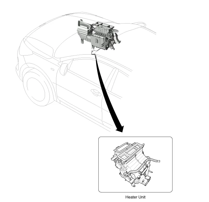
Kia Rio: Heater / Heater Unit
Components and components location
| Component Location |
| Components |
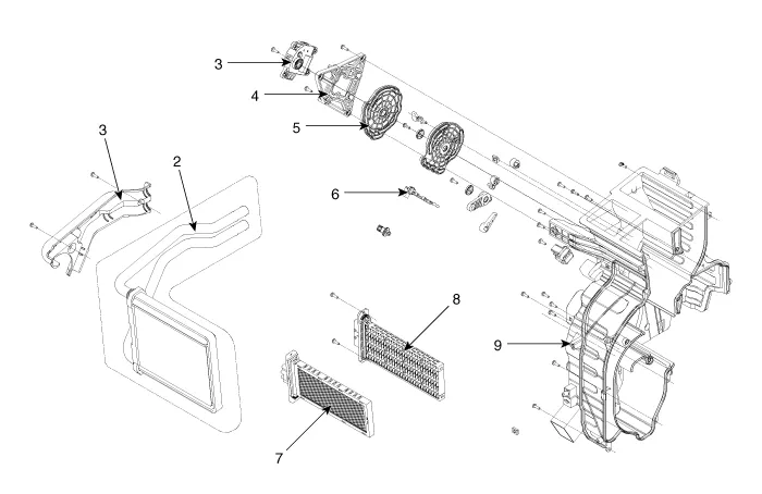
| 1. Heater pipe cover 2. Heater core 3. Mode control actuator 4. Mode control actuator bracket 5. Mode control main lever |
6. Evapoerator sensor 7. PTC Heater core(350W) 8. PTC Heater core(1000W) 9. Heater case |
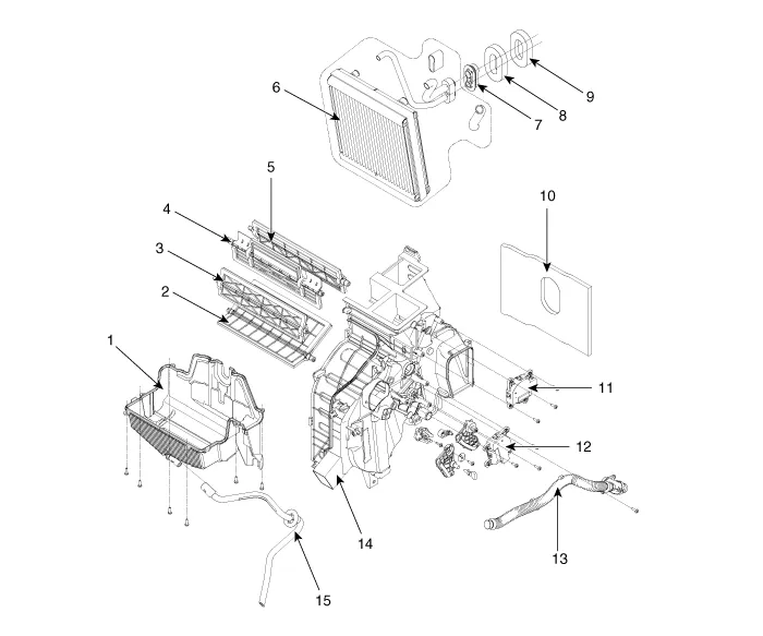
| 1. Heater lower case 2. Door assembly (TEMP) 3. Door assembly (FOOT) 4. Door assembly (VENT) 5. Door assembly (DEF) 6. Evapoerator core 7. Evapoerator Flange 8. Seal |
9. Seal (Non A/C) 10. NVH Pad 11. Defog actuator 12. Tempature control actuator 13. Aspirator hose 14. Heater case (RH) 15. Drain hose |
Repair procedures
| Replacement |
| 1. |
Disconnect the negative (-) battery terminal. |
| 2. |
Recover the refrigerant with a recovery/recycling/charging station. |
| 3. |
Drain the coolant. D 1.4 TCI-U2 (Refer to Engine Mechanical System - "Coolant") G 1.0 T-GDI-KAPPA (Refer to Engine Mechanical System - "Coolant") G 1.2 MPI-KAPPA(Refer to Engine Mechanical System - "Coolant") G 1.4 MPI-KAPPA(Refer to Engine Mechanical System - "Coolant") |
| 4. |
Remove the expansion valve (A) from the evaporator core.
|


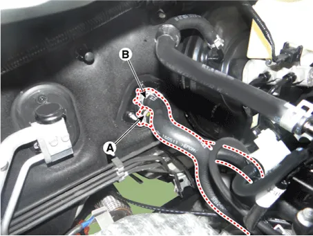
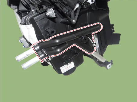
| 5. |
Disconnect the inlet (A) and outlet (B) heater hoses from the heater unit.
|

| 6. |
Remove the console assembly. (Refer to Body - "Floor Console Assembly") |
| 7. |
Remove the shift lever assembly. (Refer to Manual Transaxle System - "Shift Lever Assembly.") |
| 8. |
Lower the steering column after loosening the mounting bolts and nuts. (Refer to Steering System - "Steering Column and Shaft") |
| 9. |
Remove the wiper motor. (Refer to Body Electrical System - "Front wiper motor") |
| 10. |
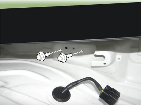
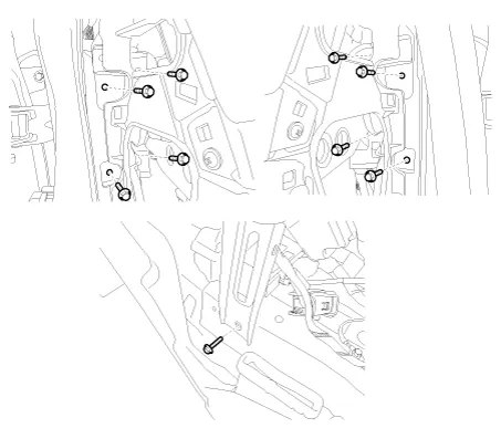
Loosen the cowl cross member mounting bolts.
|
| 11. |
Remove the crash pad. (Refer to Body - "Main Crash Pad Assembly") |
| 12. |
Loosen the cowl cross member mounting bolts and than remove the crash pad and heater & blower unit assembly.
|
| 13. |
Loosen the drain hose fixing clip under the vehicle. |
| 14. |
Disconnect the heater unit connectors. |
| 15. |
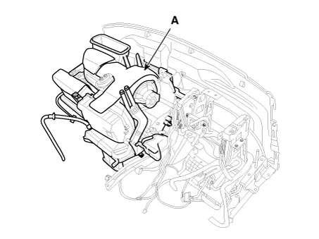
Remove the heater & blower unit (A) from the crash pad after loosening the mounting nuts.
|
| 16. |
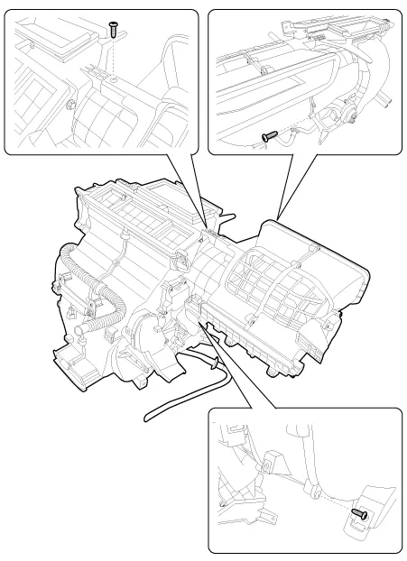
Separate the blower unit from the heater unit after loosening the screws.
|
| 17. |
Remove the heater core cover (A) after loosening the mounting screws.
|
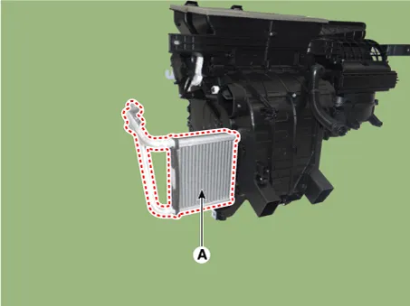
| 18. |
Pull out the heater core (A) from heater unit.
|
| 19. |
Remove the heater unit lower case (A) after loosening the mount screws.
|

| 20. |
Pull out the evaporator core (A) from heater unit.
|

| 21. |
Installation is the reverse order of removal.
|
Description and operation Description The heater unit includes mode control actuator and temperature control actuator. The temperature control actuator is located at the heater unit.
Other information:
Kia Rio 2017-2023 YB Service Manual: Rear Glass Defogger
C
Kia Rio 2017-2023 YB Service Manual: Blower Resistor (MANUAL)
Repair procedures Inspection 1. Measure the resistance between the terminals. 2. The measured resistance is not within specification, the blower resistor must be replaced. (After removing the resistor) Replacement 1.
Categories
- Manuals Home
- Kia Rio Owners Manual
- Kia Rio Service Manual
- Heating,Ventilation, Air Conditioning
- Engine Mechanical System
- Body Electrical System
- New on site
- Most important about car
