Kia Rio: Driveshaft and axle / Front Hub / Knuckle
Components and components location
| Components |
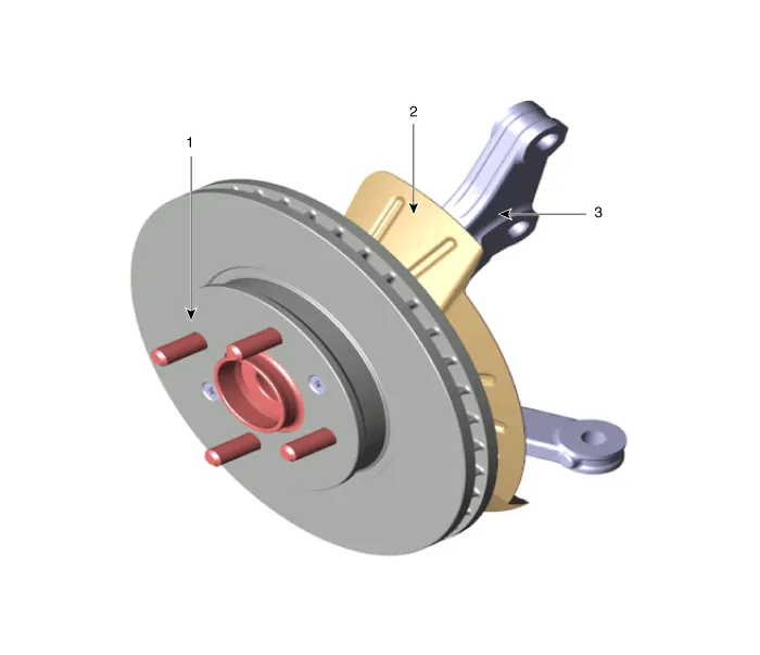
| 1. Front disc 2. Dust cover |
3. Knuckle |
Repair procedures
| Removal |
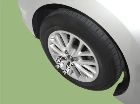
| 1. |
Remove wheel nuts, front wheel and tire from front hub.
|

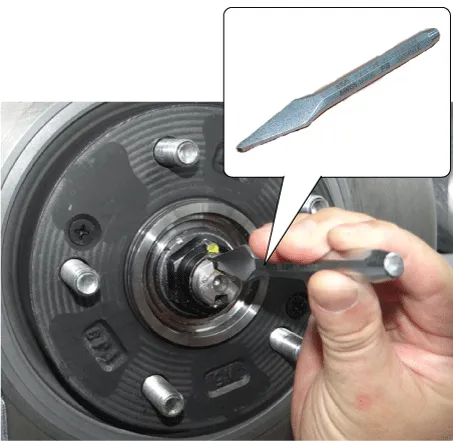
| 2. |
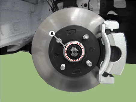
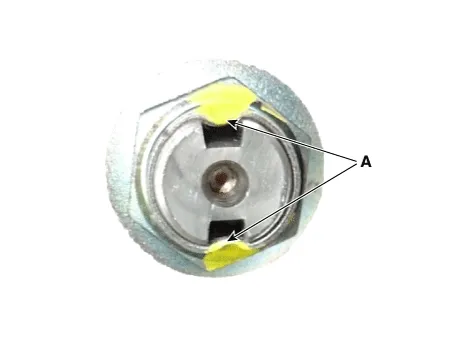
By hammering on a chisel, unlock the driveshaft lock hub nut caulking.
|

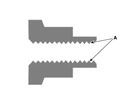
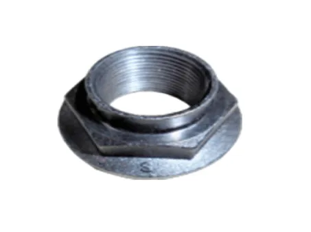
| 3. |
Remove the caulking nut (A) from the front axle.
|
| 4. |
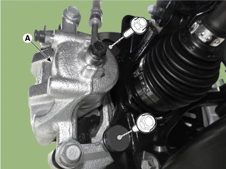
Remove the brake caliper mounting bolts, and then hold the brake caliper assembly (A) with wire.
|
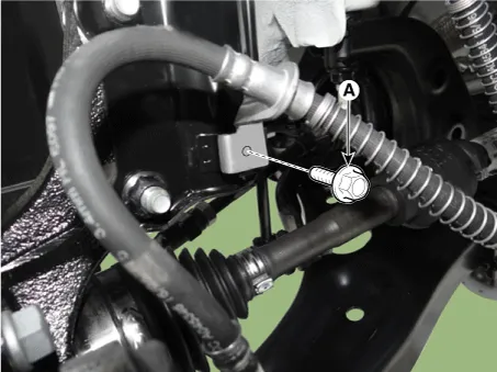
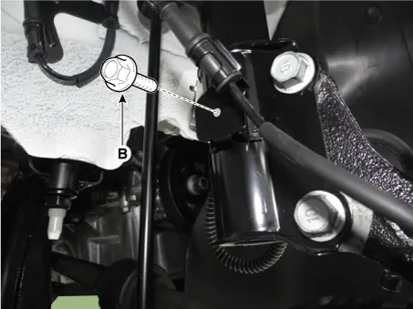
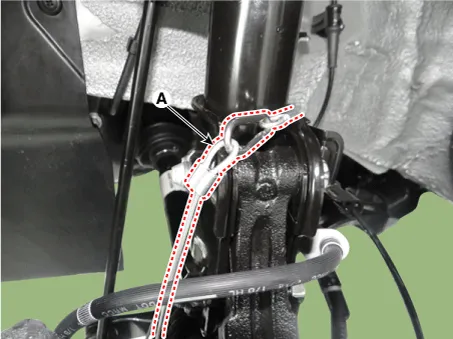
| 5. |
Remove the brake caliper hose bracket bolt (A) and wheel speed sensor bracket bolt (B).
|
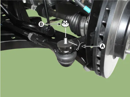
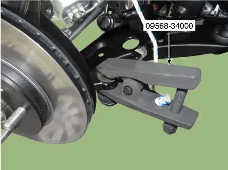
| 6. |
Remove the tie rod end ball joint from the knuckle by using the SST (09568-34000).
|
| 7. |
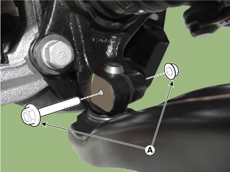
Remove the lower arm bolt and nut (A).
|
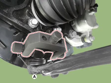
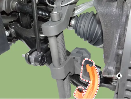
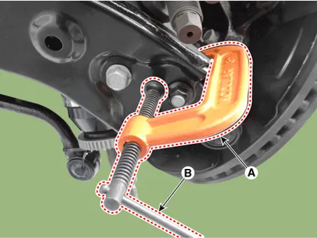
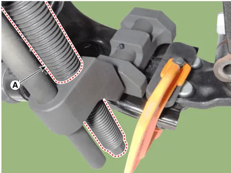
| 8. |
Remove the front lower arm from the front knuckle using the SST (0K545-A9100).
|
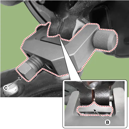

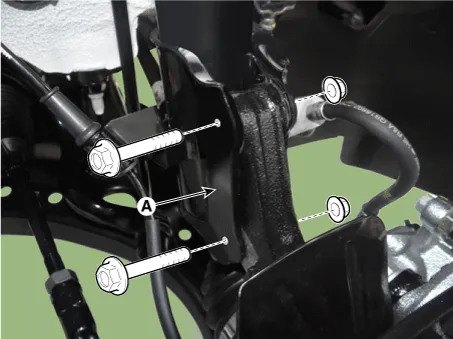
| 9. |
Loosen the bolts and then remove the strut assembly (A) from the knuckle.
|
| Inspection |
| 1. |
Check the hub for cracks and the splines for wear. |
| 2. |
Check the brake disc for scoring and damage. |
| 3. |
Check the knuckle for cracks |
| 4. |
Check the bearing for cracks or damage. |
| Disassembly |
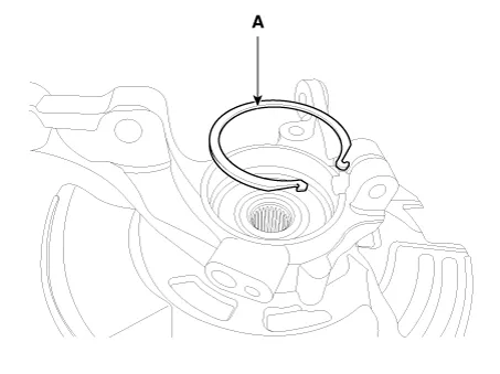
| 1. |
Remove the snap ring (A).
|
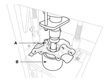
| 2. |
Remove the hub assembly from the knuckle assembly.
|
| 3. |
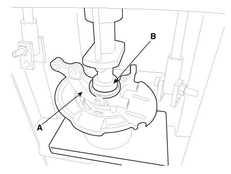
Remove the hub bearing inner race from the hub assembly.
|
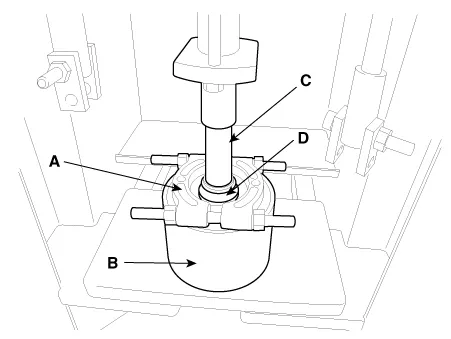
| 4. |
Remove the hub bearing outer race from the knuckle assembly.
|
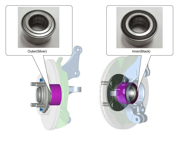
| 5. |
Replace hub bearing with a new one. |
| Reassembly |
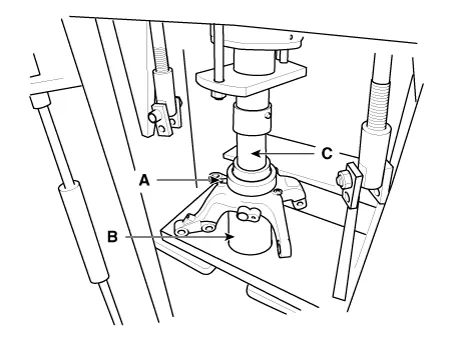
| 1. |
Install the hub bearing to the knuckle assembly.
|
| 2. |
Install the hub assembly to the knuckle assembly.
|
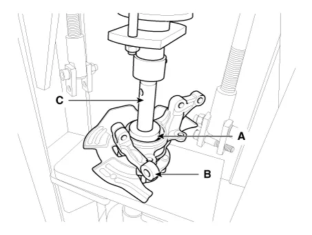
| 3. |
Install the snap ring (A).
|
Specifications Specification Engine T/M Joint type Max. permissible angle Outer Inner Outer Inner Gasoline 1.
Other information:
Kia Rio 2017-2023 YB Service Manual: Hazard Lamp Switch
Repair procedures Inspection 1. Check for continuity between terminals. If the continuity is not as specified, replace the hazard lamp switch. No. Description No.
Kia Rio 2017-2023 YB Service Manual: Front Washer Motor
Repair procedures Inspection Front Washer Motor 1. With the washer motor connected to the reservoir tank, fill the reservoir tank with water. • Before filling the reservoir tank wi
Categories
- Manuals Home
- Kia Rio Owners Manual
- Kia Rio Service Manual
- Heating,Ventilation, Air Conditioning
- Clutch System
- Maintenance
- New on site
- Most important about car
