Kia Rio: ESC (Electronic Stability Control) System / ESC Control Module
Components and components location
| Components |
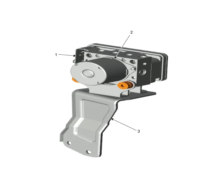
| 1. ESC control module connector
2. ESC control module |
3. ESC bracket |
Repair procedures
| Removal |
| 1. |
Turn ignition OFF and disconnect the negative (-) battery cable. |
| 2. |
Remove the brake fluid from the master cylinder reservoir with a syringe.
|

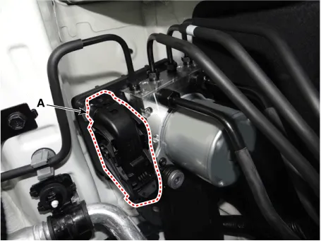
| 3. |
Pull up the lock of the ESC connector (A) and then disconnect the connector.
|
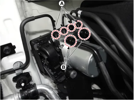
| 4. |
Disconnect the brake tubes from the ECS by unlocking the nuts counterclockwise with a wrench.
|
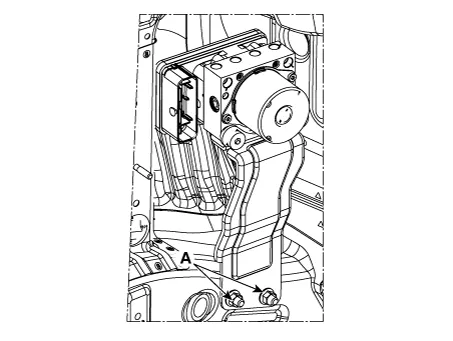
| 5. |
Loosen the ESC control module bracket nuts (A), and then remove the ESC control module bracket.
|
| Installation |
| 1. |
Install in the reverse order of removal. |
| 2. |
After installation, bleed the brake system. (Refer to Brake system - "Brake System") |
| 3. |
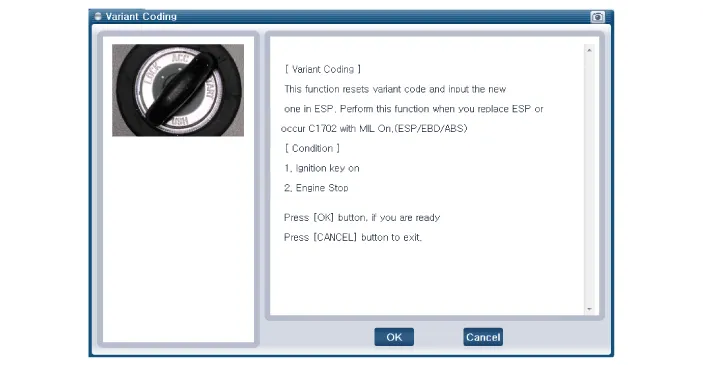
Conduct the Variant coding. |
| 4. |
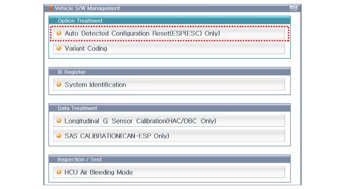
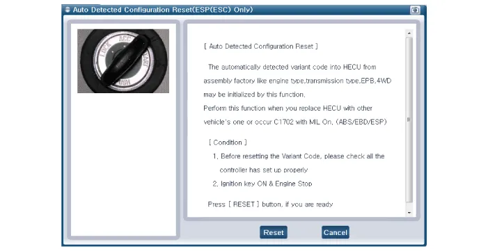
Conduct the Auto Detected Sensor Calibration. |
| 5. |
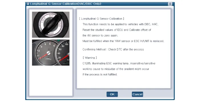
Conduct the Longitudinal G Sensor Calibration. |
| Diagnostic procedure by using diagnostic device |
Perform diagnostic procedure by using diagnostic device as shown below:
Connect self-diagnosis connector (16pins) located under the driver side crash pad to self-diagnosis device, and then turn the self-diagnosis device after key is ON.
Select the "vehicle model" and "ABS/ESC" on GDS vehicle selection screen, then select OK.
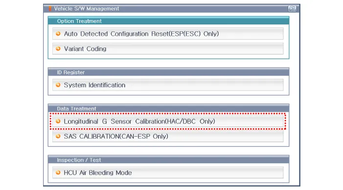
| [Variant Coding] |
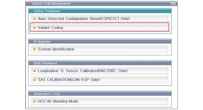
| [Auto Detected Sensor Calibration] |
| [Longitudinal G Sensor Calibration] |
Components and components location Components 1. ESC control module 2. Front wheel speed sensor 3. Rear wheel speed sensor Description and operation Description of ESC Electronic Stability Control (ESC) recognizes critical driving conditions, such as panic reactions in dangerous situations, and stabilizes the vehicle by wheel-individual braking and engine control intervention.
Components and components location Components 1. Front wheel speed sensor connector 2. Front wheel speed sensor Repair procedures Removal 1.
Other information:
Kia Rio 2017-2023 YB Service Manual: Antenna Coil
Repair procedures Removal 1. Disconnect the negative (-) battery terminal. 2. Remove the crash pad lower panel. (Refer to Body - "Crash Pad Lower Panel") 3. Remove the steering column upper and lower shroud panel.
Kia Rio 2017-2023 YB Service Manual: Vanity Lamp
Repair procedures Removal 1. Disconnect the negative (-) battery terminal. 2. Detach the vanity lamp (A) using a flat-tip screwdriver. 3. Disconnect the vanity lamp connector (A).
Categories
- Manuals Home
- Kia Rio Owners Manual
- Kia Rio Service Manual
- Maintenance
- Maintenance
- Emission Control System
- New on site
- Most important about car
