Kia Rio: Air Conditioning System / Condenser
Repair procedures
| Inspection |
| 1. |
Check the condenser fins for clogging and damage. If clogged, clean them with water, and blow them with compressed air. If bent, gently bend them using a screwdriver or pliers. |
| 2. |
Check the condenser connections for leakage, and repair or replace it, if required. |
| Replacement |
| 1. |
Recover the refrigerant with a recovery/recycling/charging station. |
| 2. |
Disconnect the negative (-) battery terminal. |
| 3. |
Remove the front bumper. (Refer to Body - "Front Bumper Assembly") |
| 4. |
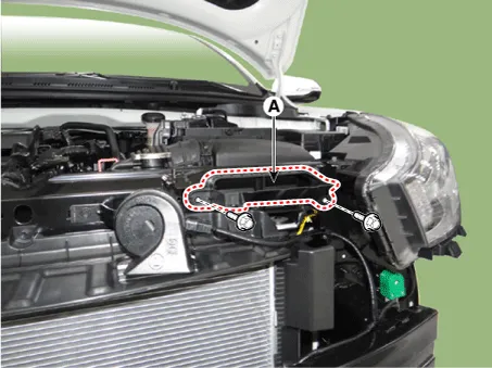
Remove the air intake shield (A) after loosening the bolts.
|
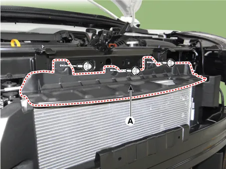
| 5. |
Remove the air upper guard (A) after loosening the bolts.
|
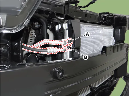
| 6. |
Remove the discharge line (A) and liquid line (B) after loosening the nuts.
|
| 7. |
Loosen the mounting pin - type retainers and bolts, remove the side air guard (A).
|
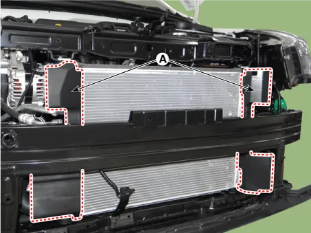
| 8. |
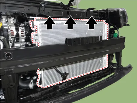
Remove the condenser.
|
| 9. |
Installation is the reverse order of removal.
|

Description and operation Description The compressor is the power unit of the A/C system. It is located on the side of engine block and driven by a V-belt of engine.
Repair procedures Replacement 1. Remove the condenser. 2. Remove the cap (B) on the bottom of the condenser with L wrench (A).
Other information:
Kia Rio 2017-2023 YB Service Manual: Lighting System
Specifications Specification Item Type Bulb Watt (W) Front Headlamp Halogen Low/High H4 LL 55/60 Turn signal lamp PY21W 21 Position lamp W5W
Kia Rio 2017-2023 YB Service Manual: Receiver-Drier
Repair procedures Replacement 1. Remove the condenser. 2. Remove the cap (B) on the bottom of the condenser with L wrench (A). Tightening torque : 2.7~3.2 N.m (0.28~0.
Categories
- Manuals Home
- Kia Rio Owners Manual
- Kia Rio Service Manual
- Cooling System
- Engine Mechanical System
- Maintenance
- New on site
- Most important about car
