Kia Rio: Brake System / Stop Lamp Switch
Components and components location
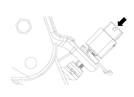
| Components |
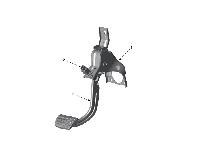
| 1. Brake pedal member assembly
2. Stop lamp switch |
3. Brake pedal arm |
Schematic diagrams
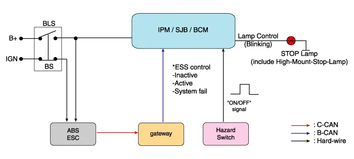
| Schematic Diagram |
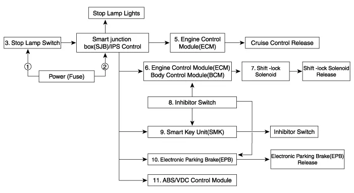
| System circuit diagram |
| Terminal function |

|
Terminal |
Description |
|
1 |
IGN1 |
|
2 |
Engine Control Module (ECM) |
|
3 |
B+ |
|
4 |
Stop Lamp |
Troubleshooting
| Troubleshooting |
| 1. |
Part diagnosis
|
| 2. |
Symptom diagnosis
|
| 3. |
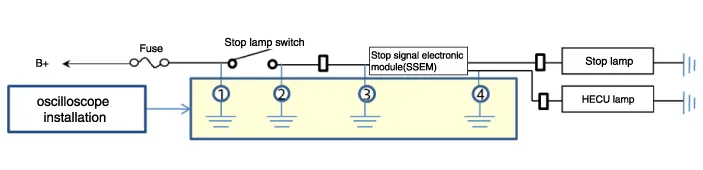
Stop lamp switch system diagnosis
SSEM : Stop Signal Electronic Module |
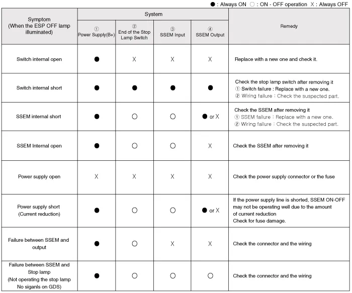
| 4. |
Refer to DTC guide when the related DTC codes are displayed. |
Repair procedures
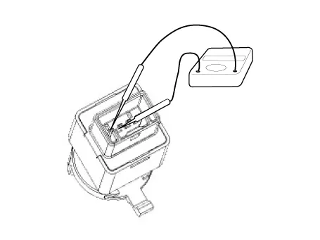
| Adjustment |
| 1. |
Confirm the gap between stop lamp switch and bracket.
|
| 2. |
If the gap between stop lamp switch and bracket is not between 1.0 - 2.0 mm (0.04 - 0.08 in), check the mounting clip and other parts around the stop lamp. |
| 3. |
If everything is normal, reinstall the stop lamp switch and check the clearance again. |
| Inspection |
| 1. |
Check the stop lamp switch.
|
| Replacement |
| 1. |
Switch "OFF" ignition and disconnect the negative (-) battery terminal. |
| 2. |
Remove the crash pad lower panel. (Refer to Body - "Crash Pad Lower Panel") |
| 3. |
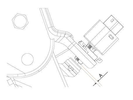
Disconnect the brake lamp switch connector (A).
|

| 4. |
Pull the locking plate (A) as indicated by the arrow.
|
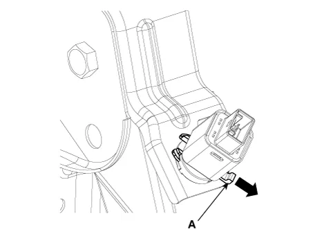
| 5. |
Turn brake switch 45° counterclockwise and remove it.
|

| 6. |
Fix the brake pedal arm and insert fully the brake switch so that the contact part is invisible.
|
| 7. |
After inserting, turn the brake switch 45° clockwise, and then assemble locking plate by pushing.
|

| 8. |
Connect the brake lamp switch connector (A).
|
| 9. |
Install the crash pad lower panel. (Refer to Body - "Crash Pad Lower Panel") |
Components and components location Components 1. Shoe hold down pin 2. Shoe adjuster 3. Upper return spring 4. Adjusting lever 5.
Components and components location Components 1. Parking brake lever 2. Equalizer assembly 3. Rear parking brake cable Repair procedures Removal Rear Disc Brake Type The parking brake cables must not be bent or distorted.
Other information:
Kia Rio 2017-2023 YB Service Manual: License Lamps
Repair procedures Removal 1. Disconnect the negative (-) battery terminal. 2. Remove the license lamp assembly (A) after pressing the locking pin. 3. Disconnect the license lamp connector (A).
Kia Rio 2017-2023 YB Service Manual: Power Mosfet (FATC)
Repair procedures Inspection 1. Turn the ignition switch ON. 2. Manually operate the control switch and measure the voltage of blower motor. 3. Select the control switch to raise voltage until high speed.
Categories
- Manuals Home
- Kia Rio Owners Manual
- Kia Rio Service Manual
- Brake System
- Motor Driven Power Steering
- Steering System
- New on site
- Most important about car
